 |
|||
|
|
|||
|
Page Title:
IGV SYSTEM BINDS WHEN IGV ACTUATOR LEVER IS MOVED BY HAND-continued |
|
||
| ||||||||||
|
|
 TM
9-2835-255-34
-
3-2. TROUBLESHOOTING CONTINUED
E S - 2 6 . IGV SYSTEM BINDS WHEN IGV
g. INLET GUIDE VANE (IGV)
ACTUATOR LEVER IS MOVED BY HAND.
S Y S T E M - CONTINUED
- CONTINUED
CONTINUED FROM STEP 9
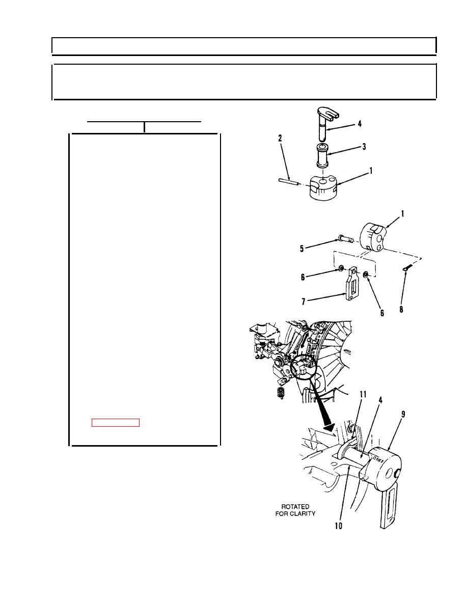
A.
Place bellcrank (1) on
flat surface. Start new
spring pin (2) into
bellcrank (1).
B. Put bushing (3) on inlet
guide control (4), and
place inlet guide
control (4) Into
bellcrank (1).
NOTE
When seated, spring pin (2)
should extend about 1/4-
inch out of bellcrank (1).
C.
Use 3\32-inch punch to
install spring pin (2)
in bellcrank (1) and
inlet guide control (4)
until seated.
D.
Install pin (5), two
washers (6), link (7),
and new cotter pin (8).
E.
Install bellcrank, link
and control (9) in lower
housing (10), making
sure that fork (11) of
inlet guide control (4)
is positioned around
ball joint on IGV unison
ring.
F.
Install low pressure
compressor housing
assembly (top half)
G.
Verify problem is
solved.
END OF TASK
3-219
Change 5
|
|
Privacy Statement - Press Release - Copyright Information. - Contact Us |