 |
|||
|
|
|||
|
Page Title:
CAM FOLLOWER/PUSH ROD REMOVAL/INSTALLATION. |
|
||
| ||||||||||
|
|
 TM 9-2815-224-34&P
Valve Mechanism Maintenance Instructions (Cont)
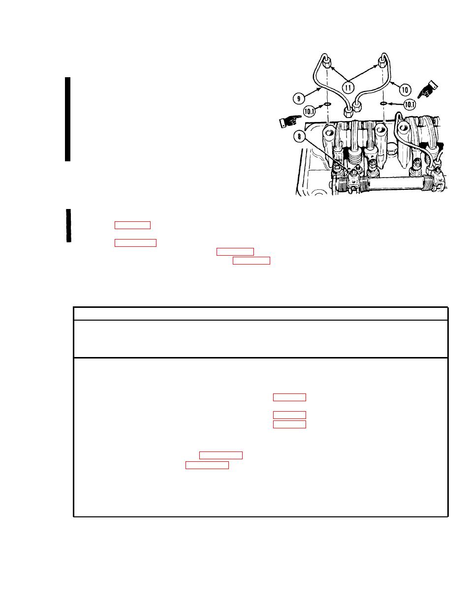
Remove caps from four fuel line
(6)
connectors (8).
NOTE
Preformed packings must be installed dry. Do
not apply oil.
Install two fuel tubes (9 and 10) and four
(7)
preformed packings (10.1).
Tighten four nuts (11) to 160 lb-in.
(8)
(18.1 Nm) using fuel line nut wrench.
Loosen four nuts (11) slightly and
(9)
retighten to 10 lb-ft (14 Nm).
f.
Follow-on Maintenance.
Install throttle delay (right front rocker arm only) (engines equipped with throttle delay only)
(1)
(1.1) Install fuel modulator (left rear rocker arms only) (engines equipped with fuel modulator only)
(4) Install rocker cover (TM 9-2320-279-20).
(5) Connect batteries (TM 9-2320-279-20).
END OF TASK
7-6. CAM FOLLOWER/PUSH ROD REMOVAL/INSTALLATION.
This task covers:
c. Follow-on Maintenance
a. Removal
b. Installation
INITIAL SETUP
Equipment Condition
Models
Condition Description
TM or Para
All
Cylinder head removed from
Test Equipment
engine.
None
Rocker arms removed.
Exhaust valve bridge
Special Tools
removed.
Gage, feeler FB310B
Special Environmental Conditions
Supplies
None
Tags, identification, Item 61, Appendix C
Oil, lubricating, Item 48, Appendix C
General Safety Instructions
None
Personnel Required
MOS 63W, Wheel vehicle repairer
Level of Maintenance
References
Direct Support
None
Change 2
|
|
Privacy Statement - Press Release - Copyright Information. - Contact Us |