 |
|||
|
|
|||
|
|
|||
| ||||||||||
|
|
 *TM 9-2815-213-34
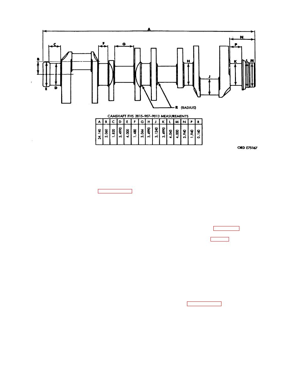
Figure 3-5. Crankshaft dimensions.
(2) Alternately torque both bolts in each cap to
3-12. Installation
340-350 ft. lbs.
a. Lay upper main bearing shells in block engaging
(3) Fully loosen all bolts to relieve tension.
shell tang in recess. Refer to paragraph 2-ll.p. (6) and
(4) Alternately torque both bolts in each cap to
(7).
80-90 ft. lbs.
b. Coat shells with GAA.
(5) Alternately torque both bolts in each cap to
c. Install shaft in block. Refer to paragraph 2-11.p.
170-180 ft lbs.
(5) for installation instructions.
(6) Scribe each cap in line with a corner hex of
d. Install upper thrust half-rings in rear main
each bolt head.
bearing with grooved side next to shaft flange.
(7) Advance each bolt 60 degrees alternately
e. Coat lower bearing shells with GAA and snap
on each cap in 30 degree increments.
into position in bearing caps.
k. Check shaft clearance against limits specified in
f, Install lower main bearing thrust half-rings over
repair and rebuild standards (para. 3-176) as follows:
dowels in bearing cap.
(1) Using a suitable holder attach a dial
g. Install bearing caps over shaft.
indicator to rear of block (fig. 3-6) with gage plunger
resting against flange face.
NOTE
(2) Using a pry bar move shaft to front of block.
Main
bearing
caps
are
not
(3) Set gage to zero.
interchangeable, insure that numbers
(4) Move shaft to front of block and observe
stamped on caps correspond with
gage reading.
numbers stamped on block.
NOTE
h. Lubricate threads of the bearing cap bolts with
If clearance, with a new shaft and thrust
OE-10 lubricant.
rings, is less than 0.005-inch loosen all
i. Install bolts and plain washers in each cap and
bearing cap bolts and move shaft to
engage threads by hand.
front of block then to rear of block.
j. Tighten bolts as follows:
Refer to paragraph 3-12.j., and
(1) Alternately torque both bolts in each cap to
150-160 ft. lbs.
3-4
|
|
Privacy Statement - Press Release - Copyright Information. - Contact Us |