 |
|||
|
|
|||
|
Page Title:
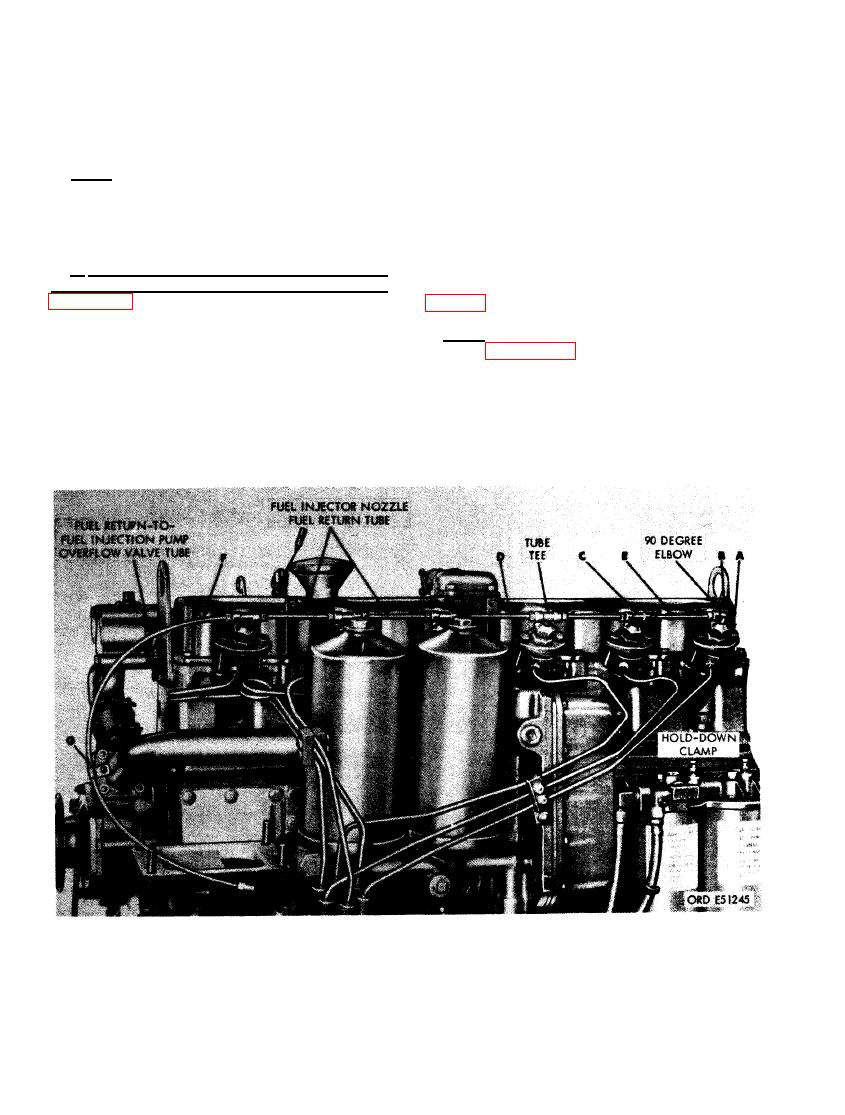
FIGURE 506. INSTALLING FUEL INJECTOR NOZZLE AND HOLDER FUEL RETURN TUBES. |
|
||
| ||||||||||
|
|
 on nozzle holder with clamp properly posi-
90 degree elbow in cylinder No. 6 nozzle holder.
tioned on dowel pin. (C) Install nozzle and
(C) Install five 1/8-inch pipe x 1/4-inch tube
holder assembly. Install remaining nozzle and
tees in the remaining nozzle holders. (D) Con-
holder assemblies as described above.
nect the long fuel injector nozzle fuel return
tube between cylinder No. 3 and 4 fuel return
Note. Use new nozzle to head gaskets when
tees. (E) Connect the remaining short fuel in-
installing nozzles. Apply a light coating of heavy
jector nozzle fuel return tubes between tees for
grease to gasket to insure proper gasket seating
cylinder No. 1 and 2, 2 and 3,4 and 5, and 5 and
and preventing gasket from sliding off the end
6. (F) Connect fuel return-to-fuel injection pump
of the nozzle.
overflow valve tube at cylinder No. 1 return tee.
(G) Install fuel return tube clip. Clip will be
b. Secure Fuel Injector Nozzle and Holder
attached to the front corner of the air com-
is installed
Assemblies and Connect Fuel Return Tubes.
when
pressor
nozzle hold-down clamps with the dowel pins
in the nozzle and holders. Install twelve 5/16-
Note. Before installing fuel injection tubes
inch lock washers and 5/16 x 2-1/2 cap screws.
refer to figure 507 for fuel injection pump
(B) Install one 1/8-inch pipe x 1/4-inch tube
port identification.
FUEL RETURN TUBES.
320
|
|
Privacy Statement - Press Release - Copyright Information. - Contact Us |