 |
|||
|
|
|||
|
Page Title:
REMOVAL OF CRANKSHAFT DAMPER AND PULLEY ASSEMBLY |
|
||
| ||||||||||
|
|
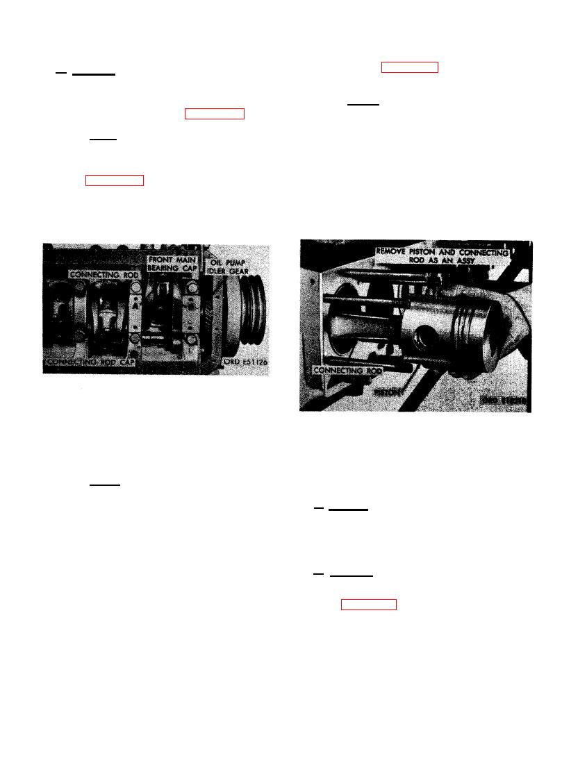
 (3) Refer to figure 285 and remove piston
b. Removal. Remove piston and connecting
and connecting rod assemblies.
rod assemblies as follows.
N o t e . Exercise care in removal of
(1) Remove carbon deposits and ridge ream
piston and connecting rods. Connecting
cylinders as shown in figure 283.
rods must not scratch or score cyl-
inder liners during removal. Rotate
Note. It will be necessary to rotate the
crankshaft as necessary to get piston
crankshaft to facilitate connecting rod
near top center and allow connecting
cap bolt removal.
rods to pass through cylinder liners.
It may be necessary to tap connecting
(2) Figure 284. (A) Remove two connecting
rod with a hammer handle, or nylon
rod bolts. (B) Remove connecting rod
dowel, to force piston and rings out of
cap and bearings.
cylinder liners.
CONNECTING ROD BEARING CAP
AND BEARING.
CONNECTING ROD.
N o t e . Keep bearings with their re-
AND PULLEY ASSEMBLY
spective cap and rod. The connecting
rod caps and connecting rods are marked
a. General. A crankshaft damper and pulley
with matched numbers (1 through 6) to
assembly is mounted to the front end of the
insure proper instillation in respective
crankshaft. The damper provides balance for
cylinders. Numbers are marked on the
the crankshaft and the pulley assembly drives
camshaft side of connecting rods. Rods
the fan drive belts and generator drive belt.
and caps must be installed with numbers
facing camshaft. Rotate crankshaft until
b. Removal. Remove crankshaft damper and
cylinder No. 1 and 6 connecting rods
pulley assembly as follows.
are at bottom dead center (bdc). Remove
cylinder No. 1 and 6 connecting rod
(1) Figure 286. (A) Remove two 3/8 x 3/4
caps. Remove piston and connecting rod
cap screws and 3/8-inch lock washers
assemblies. Remove remaining four
securing lock plate. (B) Remove lock
connecting rod caps, piston and con-
plate. (C) Remove crankshaft bolt se-
necting rod assemblies in the same
curing crankshaft damper and pulley
manner following a sequence of cyl-
assembly. (D) Remove crankshaft dam-
inders No. 2 and 5, and 3 and 4.
per pulley retaining plate.
174
|
|
Privacy Statement - Press Release - Copyright Information. - Contact Us |