 |
|||
|
|
|||
|
Page Title:
REMOVAL OF PISTON AND CONNECTING ROD ASSEMBLIES |
|
||
| ||||||||||
|
|
 137. REMOVAL OF OIL PUMP ASSEMBLY
a. General. After removing oil pump tubes
the oil pump assembly can be removed from
the front main bearing cap.
b . Removal. Remove oil pump assembly as
follows.
(1) Refer to figure 281 and remove two
hexagon head bolts securing oil pump
assembly to front main bearing cap.
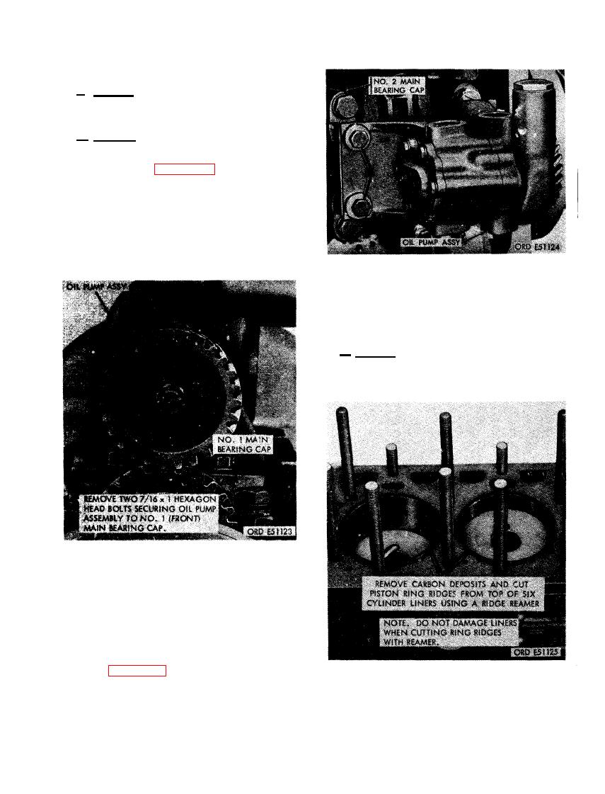
FIGURE 282. DISCONNECTING OR CON-
NECTING OIL PUMP AT NO. 2 MAIN
BEARING CAP.
ING ROD ASSEMBLIES
a . General. The piston and connecting rod
assemblies are disconnected from the crank-
shaft at the lower part of the crankcase and
removed through the top of the cylinder.
FIGURE 281. DISCONNECTING OR CON-
NECTING OIL PUMP ASSEMBLY AT
FRONT MAIN BEARING CAP.
(2) Figure 282. (A) Remove two 7/16 x 1
hexagon head bolts securing oil pump
to No. 2 front intermediate main bearing
AND CUTTING PISTON RING RIDGES
cap. (B) Remove oil pump assembly.
FROM TOP OF CYLINDER LINERS.
173
|
|
Privacy Statement - Press Release - Copyright Information. - Contact Us |
