 |
|||
|
|
|||
|
|
|||
| ||||||||||
|
|
 e. Installation. Refer to figures 112 through
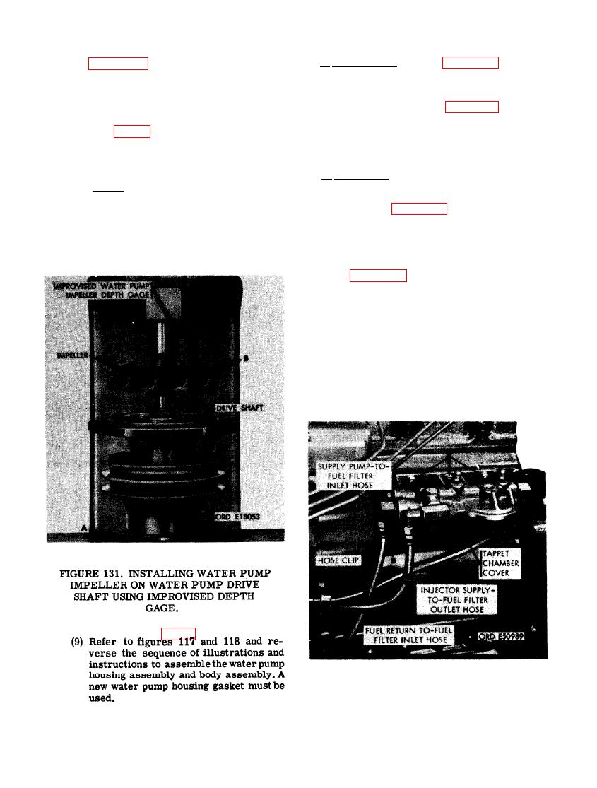
(8) Figure 131. (A) Position water pump
116 and reverse the sequence of illustrations
pulley end of drive shaft on press plate
and instructions to install the water pump as-
as shown. (B) Start water pump impeller
on drive shaft with blades facing up and
sembly. Adjust engine fan and generator drive
belt deflection as directed in figure 43.
press impeller on shaft using the im-
provised water pump impeller depth
gage (fig. 32). Measure depth of shaft
78. OIL COOLER
in impeller. Shaft distance must be
from 0.777-inch to 0.787-inch. Press
shaft to meet this distance.
a. Removal. Remove oil cooler as follows.
Note. After installing impeller on
shaft rotate impeller several times to
(1) Refer to figures 103 and 104 and follow
see that it is rotating freely. If impeller
the sequence of instructions to remove
binds, disassemble pump and replace
the primary and final fuel filter ele-
unserviceable parts.
ments.
(2) Figure 132. (A) Disconnect fuel injection
overflow hose from 3/8- inch, 90 degree
elbow. (B) Disconnect fuel supply pump-
to-fuel filter inlet hose from 3/8- inch,
90 degree elbow. (C) Disconnect fuel
injection pump supply- to- fuel filter out-
let hose from 3/8-inch, 90 degree elbow.
(D) Remove three 3/8-inch plain nuts
and 3/8- inch lock washers securing fuel
filter head to tappet chamber cover.
Remove fuel filter head.
FUEL FILTER HEAD.
100
|
|
Privacy Statement - Press Release - Copyright Information. - Contact Us |
