 |
|||
|
|
|||
|
Page Title:
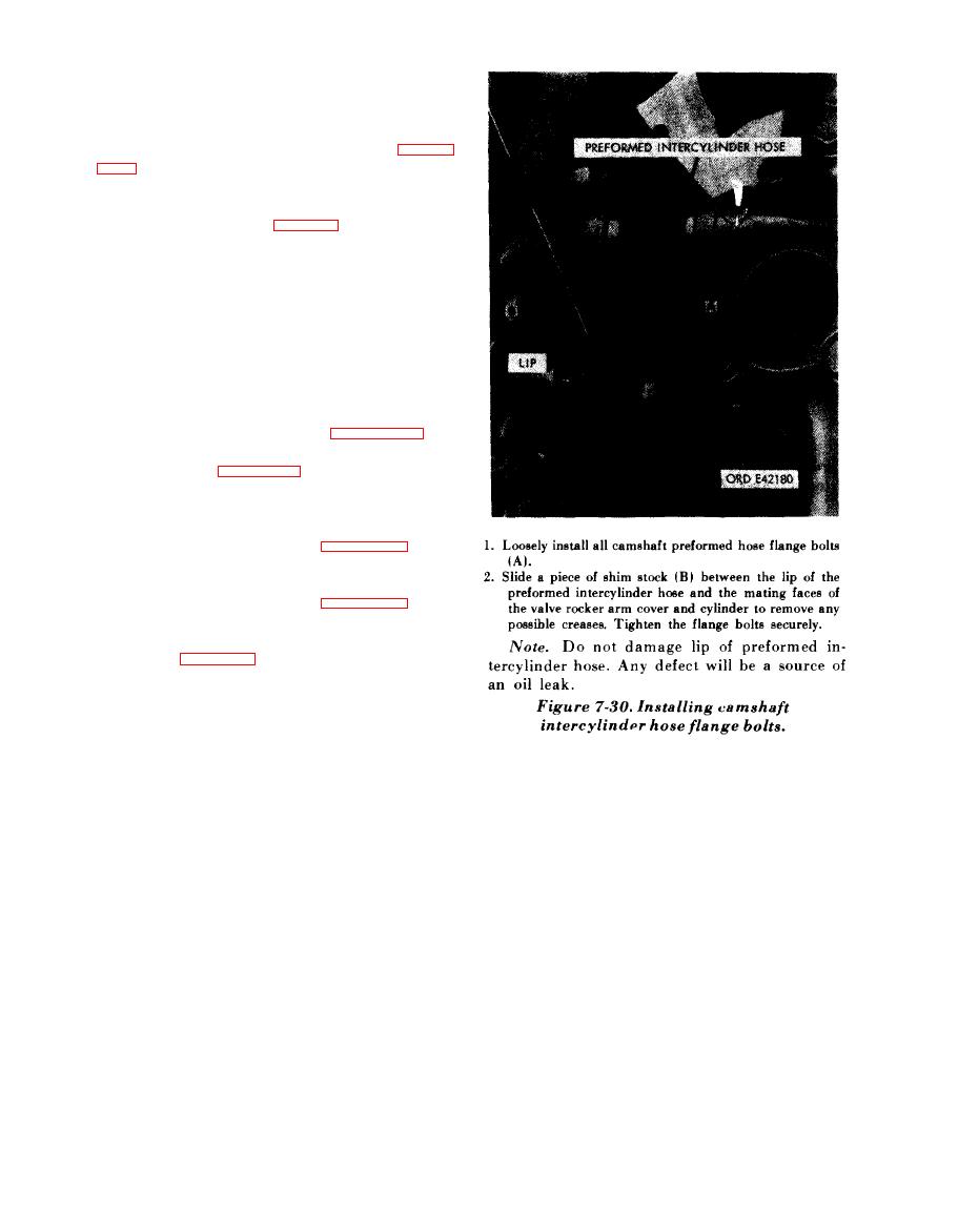
Figrue 7-30. Installing camshaft intercylinder hose flange bolts |
|
||
| ||||||||||
|
|
 c. Install Rocker Arm Covers. T h e
camshaft
lobes (cams) for cylinder No. 1R must be down
towards crankshaft, so valve rocker arm rollers
a r e on base circle of camshaft as shown in figures
The
identification
number
stamped
on
rocker
arm cover must match the number stamped on
cylinder assembly (fig. 5-105). Rocker arm
covers must always be installed on their mating
cylinder
assemblies.
Note. For
instructional
purposes.
installation
of rocker arm cover for cylinder No. 1R is used.
Remaining
covers
are
installed
in
the
same
manner.
(1) Remove protective cover from fuel
injector nozzle and holder opening in cylinder
assembly. Apply a light film of sealing com-
pound (MIL-C-10523 Ord.) to valve rocker arm
cover and install cover. Refer to figure 5-109 and
torque tighten four bolts to 275 to 325 pound-
inches. Refer to figure 5-108 and torque tighten
all bolts and cap screws to 100 pound-inches.
(2) Set valve clearance of No. 1R intake
valve to 0.010-inch using thickness gage blade -
5210-793-7898 as shown in figure 7-22.
(3) Set valve clearance of No. 1R exhaust
valve to 0.025-inch using thickness gage blade -
5210-793-7899 as shown in figure 7-23.
(4) Rotate crankshaft as necessary to
position camshaft lobes (cams) in downward
position (figs. 7-27 and 7-28) as each of the
remaining valve rocker arm covers are installed.
7-22
|
|
Privacy Statement - Press Release - Copyright Information. - Contact Us |