 |
|||
|
|
|||
|
Page Title:
Pistons and Pins, Cylinder Assemblies, Cylinder Air Deflectors Crankshaft Damper and Oil Filter Housing, and Oil Pan |
|
||
| ||||||||||
|
|
 Pistons and Pins, Cylinder A s s e m b l i e s , C y l i n d e r A i r
Deflectors,
Crankshaft Damper and Oil Filter Housing, and Oil Pan
Refer to Table 7-4 for illustrations and assembly instructions. References are listed in
the table.
Table 7-4. Pistons and Pins, Cylinder Assemblies, Cylinder Air
Deflectors, Crankshaft Damper and Oil Filter Housing, and Oil Pan
Component
References
Pistons and Pins and Cylinder Assemblies
Cylinder Air Deflectors
5-142, 5-141
Crankshaft Damper and Oil Filter Housing
5-139, 5-138
Oil Pan
a. Pistons and Pins and Cylinder Assemblies.
Refer to the instructions given in (1) and (2),
below.
Pistons.
(1)
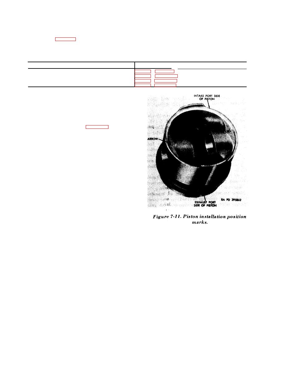
(a) The pistons are marked for iden-
tification as shown in figure 7-11 to aid in in-
stalling the pistons in their proper position. The
piston boss is stamped with an arrow and the
cylinder location (1R) to identify the cylinder
from which the piston was removed and to assure
piston will be returned to its original cylinder.
The arrows on the piston pin bosses are pointed
up, or to the exhaust outlet port. Cylinders are
stamped with piston markings at the intake valve
side (bottom) of valve rocker arm cover flange.
Markings of any piston or cylinders must be
renewed if position marks and / or arrows are
not entirely legible. Replacement piston must be
marked to the corresponding cylinder it is to be
used with. At engine overhaul, all 12 pistons and
pins are matched according to weight and cannot
vary more than 5 oz. Always keep piston pin
with its respective pin.
7-8
|
|
Privacy Statement - Press Release - Copyright Information. - Contact Us |