 |
|||
|
|
|||
|
Page Title:
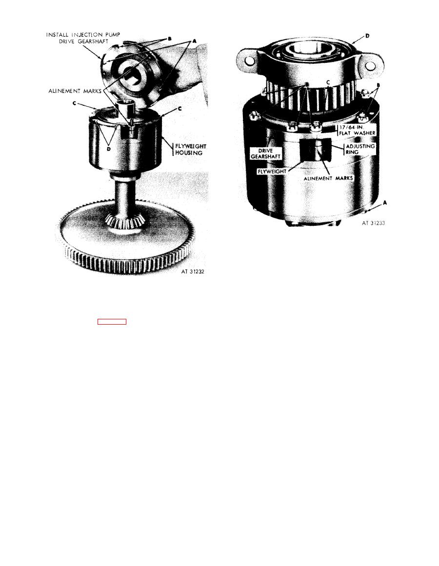
Figure 6-196. Installing injection pump drive gearshaft |
|
||
| ||||||||||
|
|
 1. Position six bolts (A) through advance vane housing
cover, housing, flyweight housing, and drive gearshaft
flange and install six slotted nuts (B) and cotter pins.
Install locking wire securing bolts.
2. Move the adjusting ring to aline scribe marks on ring,
flyweight, and drive gearshaft flange. Install two slotted
nuts (C), flat washers, and cotter pins and flyweight
1. Position the assembled injection pump drive gearshaft
pins securing adjusting ring.
on flyweight housing.
3. Install intermediate bearing support (D).
2. Mate dowel pins (A) and bolt holes (B) in gearshaft
with dowel pin holes (C) and bolt holes (D) in housing.
Figure
6-197.
Installing
advance
flyweight
(Refer to note fig. 6-193).
adjusting ring and injection pump drive
gearshaft attaching parts (adjusting
Note. The scribe line on gearshaft flange
ring secured with nuts).
and adjusting ring boss must be alined. (Refer to
note
6-175.)
Figure
6-196.
Installing
injection
pump
drive
gearshaft.
6-163
|
|
Privacy Statement - Press Release - Copyright Information. - Contact Us |