 |
|||
|
|
|||
|
Page Title:
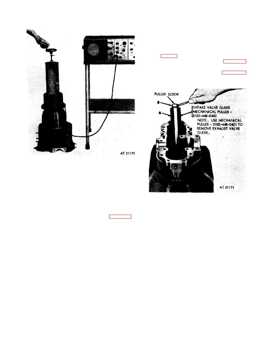
Figure 6-58. Removing intake valve guide using mechanical puller - 5120-448-0400. |
|
||
| ||||||||||
|
|
 6-33. Repair
a. Cylinder Interior.
(1) V a l v e g u i d e r e p l a c e m e n t .
(a) Replace any cracked, galled, eroded,
or scuffed intake and exhaust valve guides (14
and 37, fig. B-4) or guides which do not conform
t o limits specified in overhaul standards (table 6-
15). Replace and ream valve guides following
i n s t r u c t i o n s w h i c h a c c o m p a n y f i g u r e s 6-58
through 6-62.
installed in cylinder barrel
mounting flange.
(d) With the search fixture UPPER-
LOWER switch in the "UPPER" position,
move the search fixture probe through the full
r e m o v e d from the cylinder in the same manner.
upward and downward travel.
Mechanical puller - 5120-448-0400 is used for
N o t e . When a heavy pulse echo enters the
intake valve guide removal and mechanical
r i g h t hand edge of the gate (view F, fig. 6-53),
puller - 5120-448-0401 is used for exhaust valve
the detector has reached the maximum down-
guide reinoval.
ward travel. Any alarm indicates a crack or
defect in the cylinder. Re-inspect the defect
1. Insert
screw of mechanical puller - 5120-448-0400
suspect area. If the alarm sounds again, the
through
the valve guide and puller (A).
2. Install
nut (B) on end of puller screw and tighten to
cylinder must be scrapped.
remove
valve guide from cylinder.
Note. Should the inspection reveal an
abnormally high cylinder reject rate, the tester
using mechanical puller - 5120-448-0400.
a d j u s t m e n t s should be checked to be certain the
readings are correct.
( e ) A signal appearing immediately to the
left of the gate indicates cylinder bore roughness.
The gate start may require minute adjustment
to the right to exclude this extraneous signal.
(f) Remove the search fixture from the
c y l i n d e r , empty the water, and remove the plug
from the bottom of the cylinder bore. If the
c y l i n d e r has no defects, treat it to prevent rust.
6-66
|
|
Privacy Statement - Press Release - Copyright Information. - Contact Us |
