 |
|||
|
|
|||
|
Page Title:
Figure 6-59. Positioning intake valve guide on valve guide replacer - 5120-448-0402. |
|
||
| ||||||||||
|
|
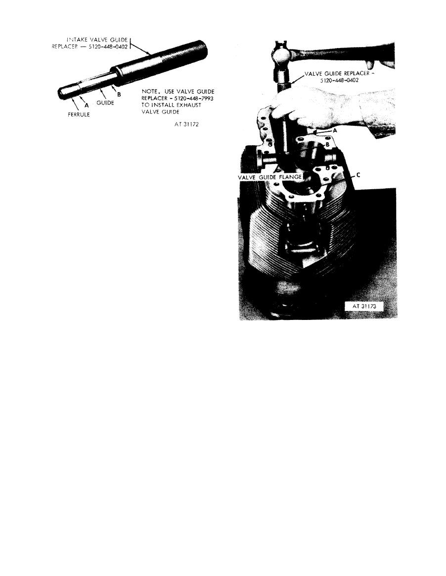 Note. The intake and exhaust valve guides are
installed in the same manner. Valve guide
replacer - 5120-448-0402 is used for replacing
intake valve guide, and valve guide replacer-
5120-448-7993 is used for replacing exhaust
valve guide.
1. Remove ferrule (A) from end of valve guide replacer
(B).
2. Place new valve guide over replacer (B) with short end
of guide entering hollow replacer handle. Replace
ferrule to retain guide or replacer.
Figure 6-59. Positioning intake valve guide
on valve guide replacer - 5120-448-0402.
1. Place assembled intake valve guide (A) and valve
guide replacer - 5120-448-0402 into valve guide bore in
cylinder.
2. Carefully drive valve guide into cylinder until flange
on guide is positioned against top face of guide bore.
3. Remove ferrule (B) from replacer and withdraw
replacer from valve guide.
4. Install exhaust valve guide (C) in the same manner
using valve guide replacer - 5120-448-7993.
Figure 6-60. Installing intake valve guide
using valve guide replacer - 5120-448-0402.
6-67
|
|
Privacy Statement - Press Release - Copyright Information. - Contact Us |
