 |
|||
|
|
|||
|
|
|||
| ||||||||||
|
|
 crankshaft.
Right
bank
rods
(marked
R)
are
installed on the damper flange side of journal.
Note. All location numbers must be visable
from the oil pan side when crankshaft and rods
are installed in the crankcase.
(3) Position connecting rod cap, with
bearing installed, on journal and mate it with the
corresponding rod. Secure rod and cap to
crankshaft with two slotted nuts.
(4) Tighten nuts to 950 pound-inches
torque, plus sufficient additional torque to aline
s l o t s in nuts with cotter pin holes in bolts.
NOTE. BEFORE REAMING,
LUBRICATE THREADS ON
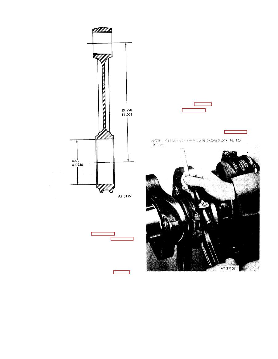
(5) Check the side clearance of each pair of
CONNECTING ROD BOLTS AND
connecting rods against limits specified in
NUTS WITH THREAD LUBRICANT,
overhaul standards (table 6-9), using a feeler
9150-663-1770 OR 9150-527-1752,
(OR EQUIVALENT) AND TIGHTEN
gage as shown in figure 6-37. Disassemble and
NUTS TO A TORQUE OF 950 LB-INS.
and bearings as
rods
replace
connecting
necessary to obtain the proper clearance.
(6)
Secure
slotted
nuts
to
connecting
rod
bolts with cotter pins as shown in figure 6-30.
dimensions.
6-18. Assembly
c. C o n n e c t i n g
Rod
Assemblies.
Note. Total weight variation between in-
dividual connecting rods on any one engine shall
not exceed 0.5 ounce.
(1) Position connecting rod bearing halves
in their respective rods and caps (fig. 6-31).
Install two connecting rod bolts in each con-
necting rod making certain each bolt is properly
clearance.
seated in the recess provided.
(2) Position rods on crankshaft in proper
location according to their identifying number.
Connecting rod Nos. 1R and 1L are assembled
on the journal at the damper flange end of the
6-41
|
|
Privacy Statement - Press Release - Copyright Information. - Contact Us |