 |
|||
|
|
|||
|
Page Title:
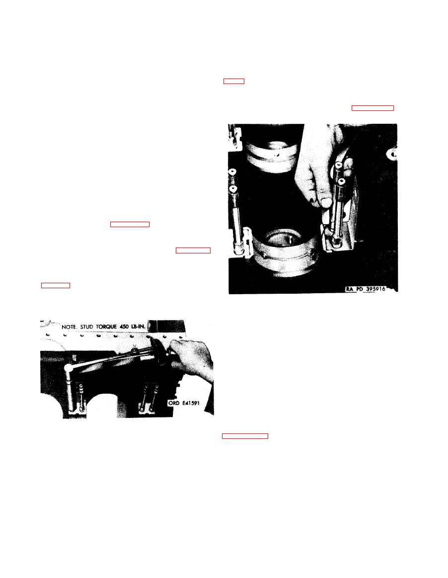
Figure 6-10. Checking torque of main bearing cap studs. |
|
||
| ||||||||||
|
|
 their
original
location
in
crankcase
and
main
(c) Fine scratches on sleeve bearing are
not cause for rejection. Pitting or any other form
bearing caps.
of destruction to the bearing surface is cause for
(d) Check clearance between upper
rejection. Replace bearings showing raised metal
bearing flange and crankcase as shown in figure
at edges of scratches.
(d) Minute pieces of metal and dirt
(e) Check clearance between the lower
particles embedded in bearing surfaces are not
main thrust bearing flange and thrust bearing
cause for rejection.
cap in the same manner as shown in figure 6-11.
Note. Do not attempt to remove such
particles. However, if a concentration of em-
bedded particles affects five percent of the
surface,
replace
the
bearing.
(4) Stud (tie rod) torque and main bearing
bore inspection.
Note. Main sleeve bearing halves should be
installed in their original location when they are
to be re-used. Use new bearings when a visual
inspection indicates bearings are unserviceable.
Use only new or serviceable bearings for main
bearing-bore check.
(a) Refer to figure 6-8 for instructions to
install crankcase on engine overhaul stand.
(b) Check main bearing cap stud torque
using a torque wrench as shown in figure 6-10.
Torque on studs must be 450 pound-inches.
Studs that do not tighten to specified torque
must be removed for further inspection. Refer to
when
replacing
studs.
Note. Never tighten main bearing studs
above
recommended torque.
1. Install upper main thrust sleeve bearing (A) into No.
4 main bearing seat of crankcase.
2. Measure clearance between bearing flange and crank-
case using feeler gage (B). Clearance should be 0.0040
to 0.0080-inch.
6-11.
Checking
clearance
between
upper main thrust bearing
flange and crankcase.
(f) Apply a light coating of engine oil,
Military Specification MIL-L-45199, to the ends
of
the
seven
main
bearing
caps
with
sleeve
bearing
halves
installed. Using crankcase
spreading tool - 5120-575-7767 as shown in
bearing cap studs.
halves in their proper locations in the crankcase.
according to the location number stamped on the
(c) Spread a thin coat of Prussian blue,
crankcase and cap. The side of the bearing cap
FSN 8010-247-8706, over steel backs of upper
marked "FLY END" must face the rear of the
and lower main sleeve bearing halves to show the
crankcase.
sleeve
bearing
contact
surface
with
the
main
(g) Apply
a
small
amount
of
antiseize
bearing bore in crankcase. Install bearings in
6-16
|
|
Privacy Statement - Press Release - Copyright Information. - Contact Us |