 |
|||
|
|
|||
|
Page Title:
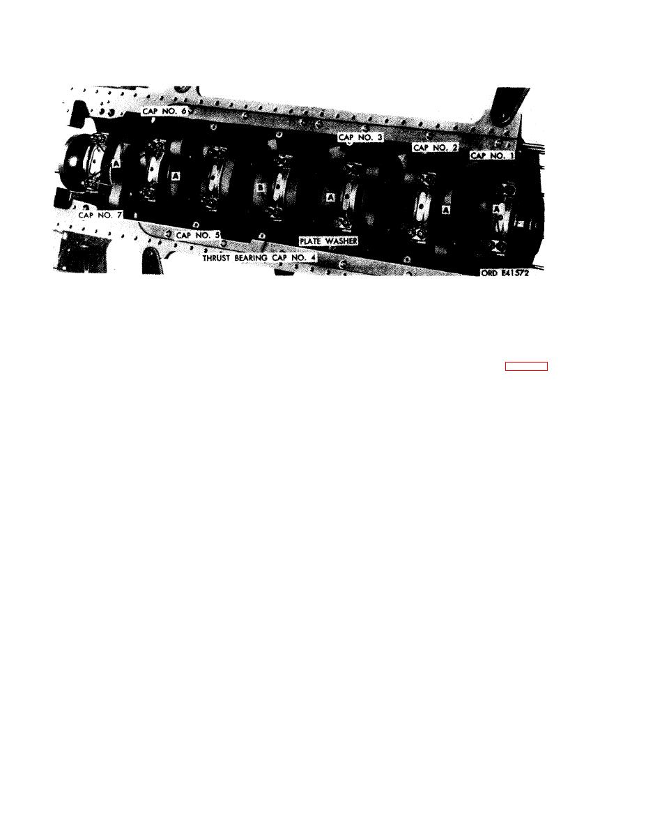
Figure 5-173. Removing or installing main bearing attaching parts. |
|
||
| ||||||||||
|
|
 Remove
2. Cut locking w ire and remove four slotted nuts (B) and
two plate washers attaching main thrust bearing cap
Note. The main bearing caps are marked 1
(No. 4 or center) to crankcase assembly.
through 7 (front to rear) to identify their
Install
locations. Identifying numbers also appear on
N o t e . Do not install locking wire until bearing
bearing web in crankcase assembly. The caps are
cap nuts have been torque tightened (para 7-5c).
not interchangeable with each other and must be
1. Apply antiseize compound (FSN 9150-663-1770) and
returned to their original positions during in-
install two plate washers and four slotted nuts (B)
stallation.
securing main thrust bearing cap (No. 4) to crankcase
assembly.
Note. Do not use a scriber or other sharp
2. Apply antiseize compound (FSN 9150-663-1770) and
instrument for marking bearing halves. It is
install 12 plate washers and 24 slotted nuts (A)
recommended that a grease pencil be used for
securing main bearing caps, numbers 1, 2, 3, 5, 6, and 7
m a t - k i n g bearing halves.
to crankcase assembly.
1. Cut locking wire and remove 24 slotted nuts (A) and
12 plate washers attaching main bearing caps, numbers
1, 2, 3, 5,6, and 7 to crankcase assembly.
5-100
|
|
Privacy Statement - Press Release - Copyright Information. - Contact Us |