 |
|||
|
|
|||
|
Page Title:
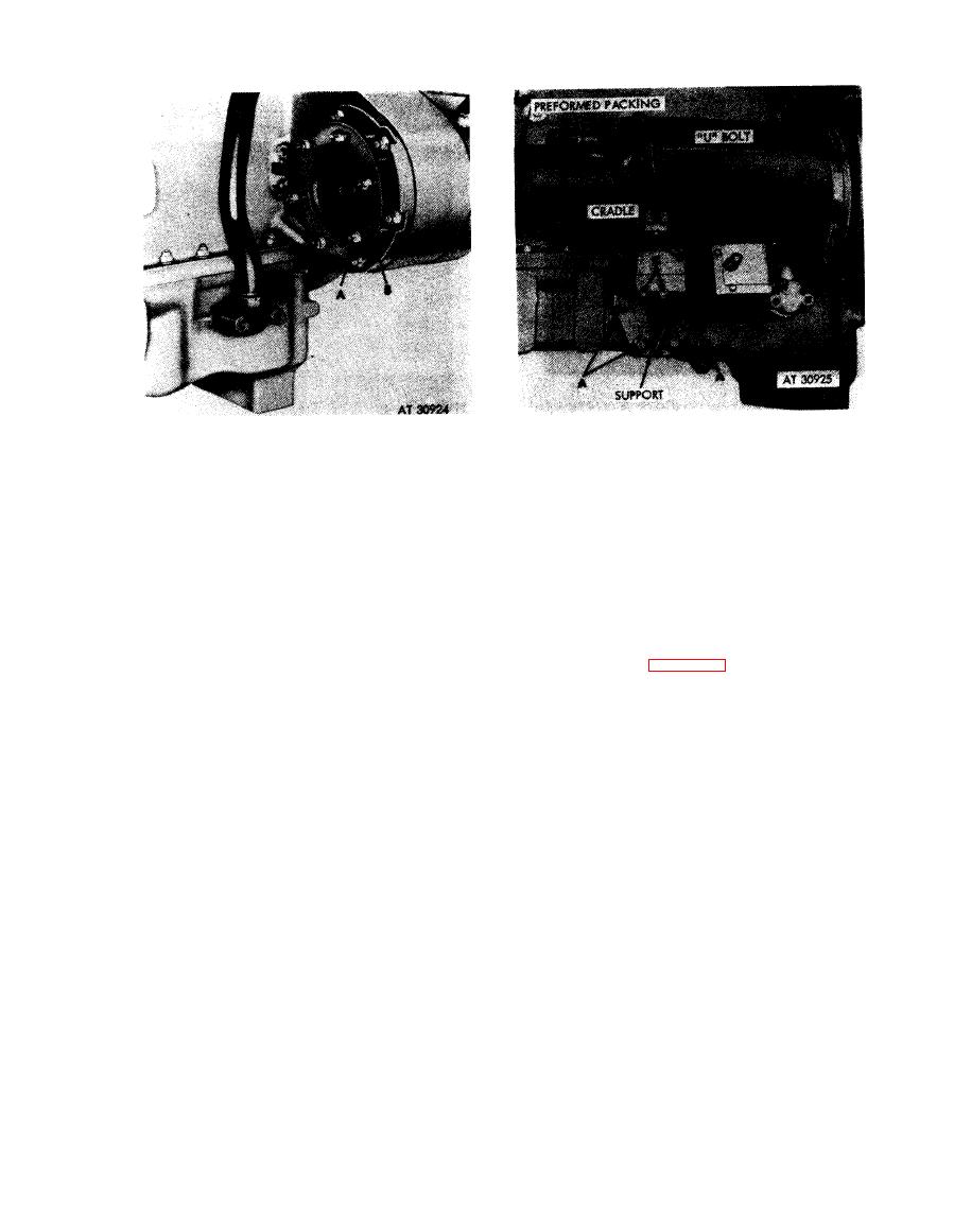
Figure 4-16. Removing or installing generator gasket. |
|
||
| ||||||||||
|
|
 It
is
important
that
the
generator
Note.
cradle, support, and "U" bolt be installed in a
Remove
manner that will not disturb generator alinement
1. Remove six self-locking nuts (A).
2. Remove and discard generator mounting gasket (B).
and still furnish adequate support to minimize
Install
vibration.
1. Position new generator mounting gasket (B) on studs.
1. Position the assembled generator cradle, support, and
2. Install, but do not tighten, six self-locking nuts (A).
"U" bolt and install four bolts (A) and flat washers.
Tighten bolts only until bolt heads engage washers
(finger-tight).
generator gasket.
2. Install "U" bolt over generator and secure with one
c l a m p i n g bar and self-locking nut (B) and torque
tighten. Torque tighten two self-locking nuts (C).
3. Torque tighten four bolts (A) and secure with locking
wire as shown in figure 4-12.
cradle, and "U" bolt.
4-9
|
|
Privacy Statement - Press Release - Copyright Information. - Contact Us |