 |
|||
|
|
|||
|
Page Title:
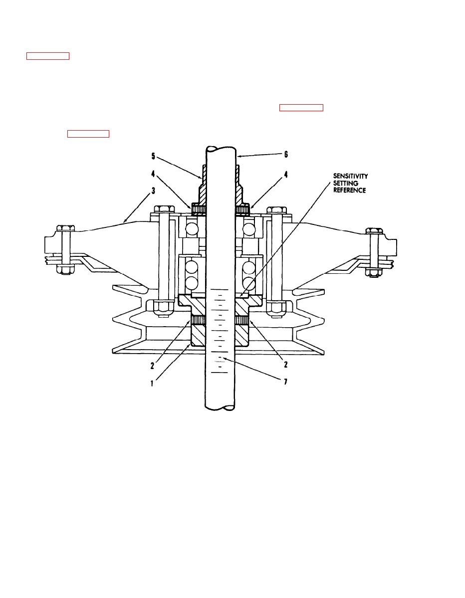
Figure 4-14. Balancer Installation - OH-13 and TH-I3 Helicopter Engine Fan Assembly. |
|
||
| ||||||||||
|
|
 TM 55-4920-201-14
coupling
d. Install
quick-disconnect
b. Carefully install engine fan assembly (3,
(7HEL053 or 7A050 kit) on arbor suspension
coupler, and suspend entire assembly free of in-
arbor. Insure that flange of pilot bushing (l) enters
terference. Note balance condition indicated by
fan hub bearing sleeve and seats squarely on outer
black indicator disc at top end of the arbor.
race of fan hub bearing.
e. For balance tolerance and application of
c. Install sleeve (5), flange downward, over
balance corrections, refer to applicable helicopter
top end of balancing arbor, and seat firmly on top
manual. (Refer to appendix A.)
surface of fan hub bearing inner race. Lock sleeve
in this position by moderate and uniform tightening
of two sleeve setscrews (4), using 3/32-inch hex
wrench (2, figure 1-18).
1. Pilot bushing (2533,
7HEL053 kit)
2. Pilot bushing setscrew
3. Engine fan assembly
4. Sleeve setscrew
5. Bushing (2530, 7HEL053
kit)
6. Balancing arbor 2516,
7HEL053 kit)
7. Arbor scale
Figure 4-14. Balancer Installation - OH-13 and TH-I3 Helicopter Engine Fan Assembly.
4-22
|
|
Privacy Statement - Press Release - Copyright Information. - Contact Us |
