 |
|||
|
|
|||
|
Page Title:
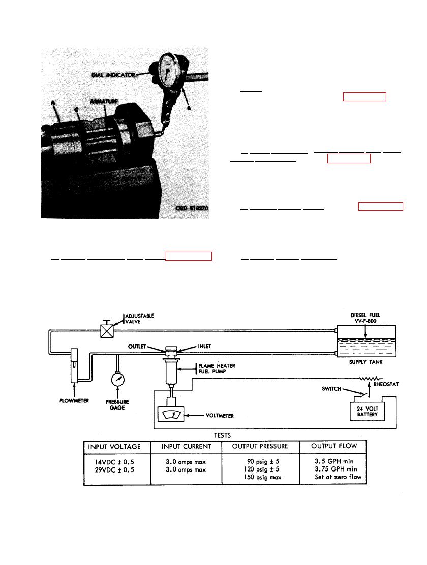
FIGURE 444. FUEL PUMP TEST EQUIPMENT. |
|
||
| ||||||||||
|
|
 Slide armature back and fourth and take end
play reading on dial indicator. Correct end
play should be from 0.003 to 0.005-inch.
Note. When end play is not between 0.003-
inch and 0.005- inch, refer to figures 441 and
442 and reverse the sequence of illustrations
and instructions to partially disassemble pump
motor. Add or subtract spacer shims as required
until proper end play is established.
c. Field Magnets, Motor Cover, and Con-
nector Receptacle. Refer to figures 421 through
424 and reverse the sequence of illustrations
and instructions to install the field magnets,
motor cover, and connector receptacle.
d. Rotary Pump Base. Refer to figures 417
through 420 and reverse the sequence of illustra-
tions and instructions to install the rotary pump
base.
PLAY USING DIAL INDICATOR.
b. Check Armature End Play. Figure 443.
e. Relief Valve Housing. Refer to figures
(A) Mount armature and associated parts in a
413 through 415 and reverse the sequence of
soft- jawed vise. (B) Set up a suitable dial in-
illustrations and instructions to install relief
dicator so arm rests on armature shaft. (C)
valve housing.
ORD E51205
279
|
|
Privacy Statement - Press Release - Copyright Information. - Contact Us |
