 |
|||
|
|
|||
|
Page Title:
FIGURE 420. REMOVING OR INSTALLING SMALL PLAIN SEAL. |
|
||
| ||||||||||
|
|
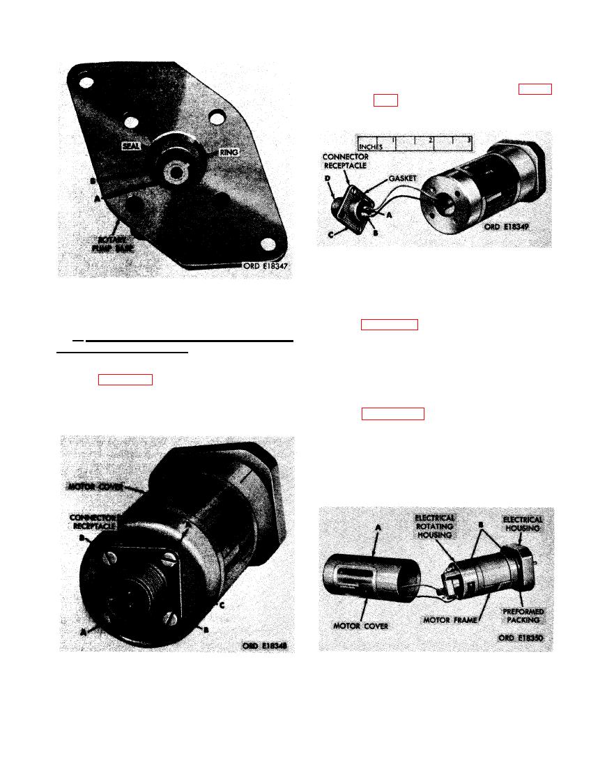 washers securing connector receptacle
to motor cover. (C) Partially pull off
connector receptacle as shown in fig-
ure 422.
CONNECTOR RECEPTACLE.
SMALL PLAIN SEAL.
(2) Figure 422. (A) Unsolder red wire from
terminal marked "A" of connector re-
c . Remove Connector Receptacle, Motor
Cover and Field Magnets. Remove receptacle,
ceptacle. (B) Unsolder black wire from
cover, and magnets as follows.
terminal marked "B" of connector re-
ceptacle. (C) Remove and discard con-
(1) Figure 421. (A) Remove two No. 4 x 7/8
nector receptacle gasket. (D) Remove
p a n head machine screws and seal
connector receptacle.
washers. (B) Remove two No. 4 x 3/8
p a n head machine screws and seal
(3) Figure 423. (A) Twist cover clockwise
to release and remove from preformed
packing. (B) Scribe alinement marks on
rotating housing and motor frame to
insure proper alinement during assem-
bly.
ASSEMBLING OF CONNECTOR RECEP-
TACLE.
MOTOR COVER.
269
|
|
Privacy Statement - Press Release - Copyright Information. - Contact Us |
