 |
|||
|
|
|||
|
Page Title:
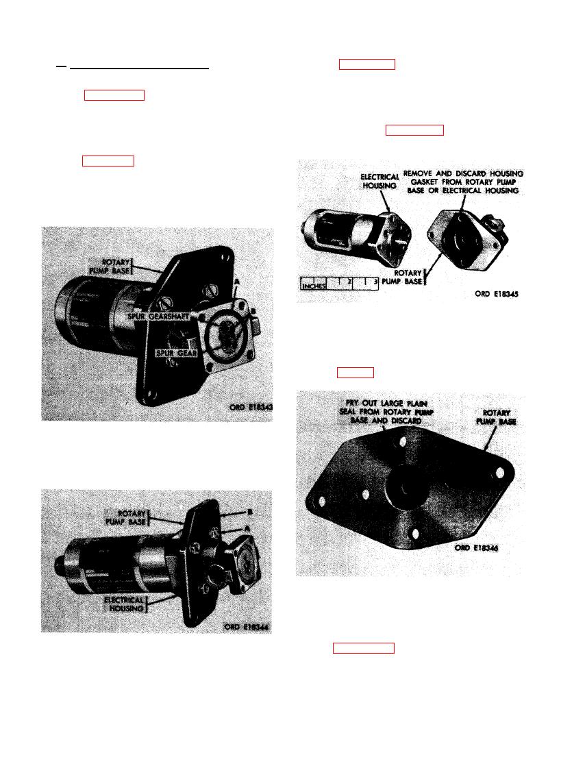
FIGURE 416. REMOVING OR INSTALLING SPUR GEAR AND SPUR GEARSHAFT. |
|
||
| ||||||||||
|
|
 b. Remove Rotary Pump Base. Remove ro-
(3) Figure 417. (A) Remove four assembled
tary pump base as follows.
washer screws securing rotary pump
base to electrical housing. (B) Remove
(1) Figure 415. (A) Remove 43/64 id x
rotray pump base from electrical hous-
0.070 thk preformed packing from relief
ing.
valve housing and discard packing. (B)
Remove gear housing from rotary pump
(4) Refer to figure 418 and remove and
base.
discard housing gasket.
(2) Figure 416. (A) Remove 43/64 id x 0.070
thk preformed packing from rotary
pump base and discard packing. (B) Re-
move spur gearshaft and spur gear from
rotary pump housing.
HOUSING GASKET.
(5) Remove large plain seal from base
SPUR GEAR AND SPUR GEARSHAFT.
LARGE PLAIN SEAL.
(6) Figure 420. (A) Pry out retaining ring
from rotary pump base and discard
retaining ring. (B) Pry out small plain
ROTARY PUMP BASE .
seal and discard seal.
268
|
|
Privacy Statement - Press Release - Copyright Information. - Contact Us |
