 |
|||
|
|
|||
|
Page Title:
CRANKSHAFT GEAR, INJECTION PUMP DRIVEN GEAR, AND CAMSHAFT GEAR |
|
||
| ||||||||||
|
|
 (9) Adjust air compressor drive belt de-
flection following instructions for fig-
ure 87.
(10) Refer to figure 41 and reverse the se-
quence of instructions to install the
engine fan and generator drive belts.
(11) Adjust engine fan and generator drive
belt deflection following instructions
for figure 43.
(12) Refer to figure 112 and reverse the se-
quence of instructions to install the en-
gine fan.
DRIVEN GEAR, AND CAMSHAFT GEAR
FRONT OIL SEAL.
a. Removal. Remove crankshaft gear, in-
jection pump driven gear, and camshaft gear
as follows.
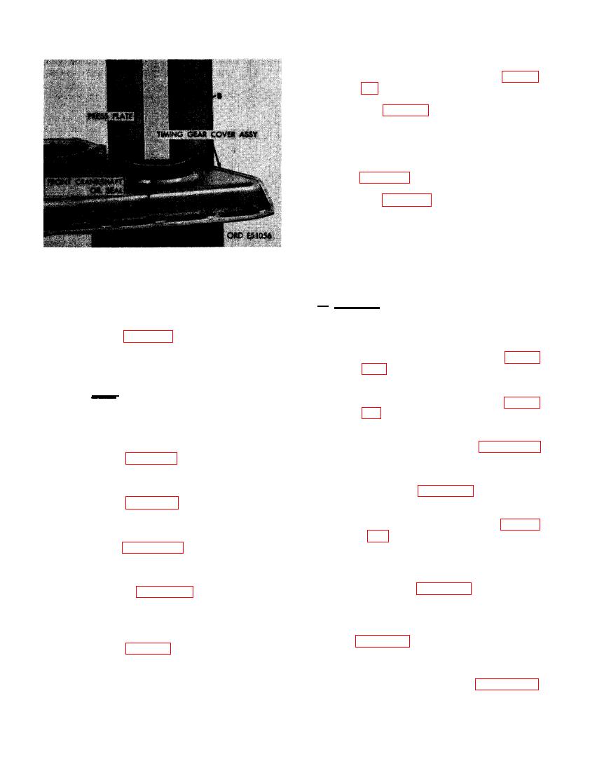
(3) Refer to figure 210 and reverse the se-
(1) Remove engine fan from water pump
quence of instructions to install timing
pulley following instructions for fig-
gear cover gasket and timing gear cover
ure 112.
assembly.
(2) Remove engine fan and generator drive
Note. The timing gear cover assembly
belts following instructions for fig-
is positioned on two locating dowel pins.
ure 41.
When installing cover, cover must be
properly positioned on pins before
(3) Remove air compressor drive belt fol-
tightening cap screws.
lowing instructions for figures 80
through 82.
(4) Refer to figure 209 and install tacho-
meter mounting adapter, drive shaft,
(4) Remove water pump assembly following
and tachometer adapter.
instructions for figures 114 through 116.
(5) Refer to figures 198 and 199 and re-
(5) Remove crankshaft damper and pulley
verse the sequence of instructions to
assembly following instructions for fig-
install oil pan gasket and oil pan.
ures 201 through 203.
(6) Refer to paragraph 96e (1) for instruc-
tions on installation of crankshaft dam-
(6) Remove oil pan and flame heater fuel
per and pulley assembly.
pump and fuel filter bracket following
instructions for figures 198 through 200.
(7) Refer to figures 114 through 116 and
reverse the sequence of illustrations
and instructions to install the water
(7) Remove tachometer drive adapter, drive
pump assembly.
shaft, and mounting adapter as shown
in figure 209.
(8) Refer to figures 80 through 82 and re-
verse the sequence of illustrations and
instructions to install air compressor
(8) Remove timing gear cover assembly
drive belt.
following instructions for figure 210.
138
|
|
Privacy Statement - Press Release - Copyright Information. - Contact Us |
