 |
|||
|
|
|||
|
Page Title:
FIGURE 42. REMOVING OR INSTALLING GENERATOR PULLEY. |
|
||
| ||||||||||
|
|
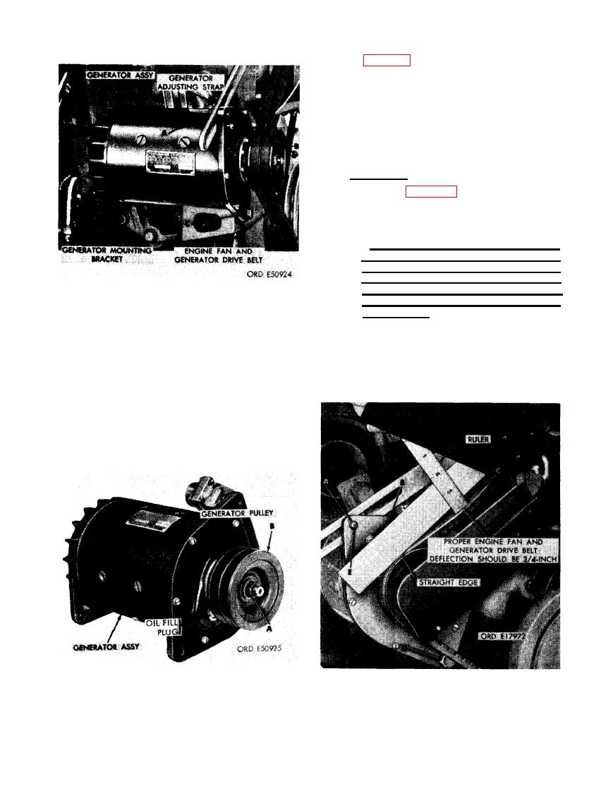 (2) Figure 42. (A) Remove 1/2- inch self-
locking nut and 1/2- inch flat washer
securing generator pulley to generator
armature shaft. (B) Remove generator
pulley from shaft using a suitable pul-
ler.
Note. Tape key in armature shaft
slot prevent loss.
--. Installation.
b
(1) Refer to figures 41 and 42 and reverse
the sequence of illustrations and in-
structions to install generator assem-
bly.
Caution: If an Autolite generator is
used for replacement, it must be lubri-
cated prior to operation. Fill drive end
oil reservoir with 0.400 fluid ounce of
engine oil, OE- 10, Specification MIL-
0-2104. Use OE- 10 oil in all ambient
temperatures.
GENERATOR ASSEMBLY AND/OR
ENGINE FAN AND GENERATOR
(2) The Delco- Remy generator is prelubri-
DRIVE BELTS.
cated and may be installed and used as
furnished. However, this generator does
remove two fan and generator drive
not include the Woodruff key. The key
belts from generator pulley. Loosen
from the original generator must be re-
generator attaching nuts to lift gener-
tained for use with the new generator.
ator. (C) Remove two 7/16-inch plain
nuts, 7/16-inch lock washers, and 7/16
x 1-1/2-inch cap screws attaching gen-
erator assembly to generator mounting
bracket. (D) Remove generator assem-
bly.
GENERATOR PULLEY.
GENERATOR DRIVE BELT DEFLECTION.
61
|
|
Privacy Statement - Press Release - Copyright Information. - Contact Us |
