 |
|||
|
|
|||
|
Page Title:
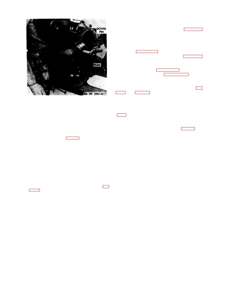
Figure 7-13. Installing cylinder assemblies on Crankcase |
|
||
| ||||||||||
|
|
 (c) When all cylinder assemblies are
installed as described and illustrated in figure 7-
13, install remaining cylinder extended washer
nuts and torque tighten the nuts alternately to
640 pound-inches. Use box wrench - 5120-678-
5287 in combination with a torque wrench as
shown in figure 5-143.
142 and 5-141.
c.
Crankshaft
Damper
and
Oil
Filter
d. Oil Pan. Refer to figures 4-125, 5-137
through 5-135 and torque tighten oil pan bolts to
175
pound-inches
and
self-locking
nuts
to
225
pound-inches. Tighten four slotted nuts (C, fig.
Note.
During overhaul operations, con-
sideration must be given to engine model, when
1. Sparingly coat cylinder stud threads (A) on crankcase
assembling oil pan to engine. Engine Model
with antiseize thread lubricant FSN 9150-527-1752 or
AVDS-1790-2-M had an oil pan (10865039, fig.
9150-663-1770.
7-14) with oil drain plugs located specifically
C a u t i o n : If lubricant is extended to face of
designed for a certain vehicle and the engine
washer nut, reliable retaining torque cannot be
model
was
not
interchangeable
with
other
obtained.
vehicles. The oil pan (10912162, fig. 7-15) on
engine Models AVDS-1790-2-AM and AVDS-
2. Rotate engine crankshaft using engine turning splined
1790-2A provides an oil drain plug location that
wrench-5120-793-7895 (fig. 5-91) until the No. 1R
connecting rod (B) is at the top of its stroke.
is accessible in all vehicles. Although limited
3.
Remove
crankcase
protector-4910-795-7951
from
numbers of early oil pans are in current use, care
cylinder No. 1R mounting studs (C) being careful not
must be taken in Depot overhaul to identify the
to allow connecting rod to forceably drop against the
early
oil
pans
and
properly
designate
engine
c r a n k c a s e cylinder mounting surface or mounting
model.
studs.
4 . Remove piston pin from piston of No. 1R cylinder
assembly and place piston and cylinder over No. 1R
c o n n e c t i n g rod. Insert piston pin (D) with plugs
through connecting rod and piston and center pin in
position. Center piston pin plugs in piston.
5. Slide cylinder (E) over piston on crankcase studs and
temporarily secure with two extended washer nuts (fig.
on crankcase.
7-10
|
|
Privacy Statement - Press Release - Copyright Information. - Contact Us |
