 |
|||
|
|
|||
|
Page Title:
Figure 5-143. Checking breaking torque of cylinder base nuts, using box wrench-5120-678-5287. |
|
||
| ||||||||||
|
|
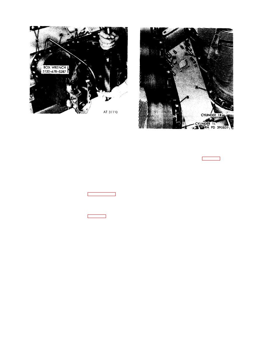 Note. Before removing cylinder assemblies, it
will be necessary to check the breaking torque of
t h e 14 nuts attaching each cylinder assembly to
crankcase assembly. This check is necessary to
Note. Before removing each cylinder
determine whether base nut stud has stretched.
assembly, the crankshaft must be turned to
All stretched studs must be replaced.
p o s i t i o n the piston of the cylinder being removed
to top dead renter. Rotate crankshaft using
splined
wrench
-5120-793-7895
and
cylinder assembly to crankcase assembly using box
observe when (connecting rod has raised piston to
wrench
(A)-5120-678-5287
in
combination
with
torque wrench. When torque required to break a nut
top dead center. Make certain each piston is
loose is less than 600 pound inches, remove nut, apply
properly positioned before attempting cylinder
antiseize compound FSN 9150-663-1770 to stud,
removal.
install nut and tighten to a torque of 600 to 660 pound
inches. When nut does not tighten to the recommended
1. With right bank cylinder assemblies in a vertical
torque, stud is stretching and must be replaced, Mark
(upright) position remove the remaining two nuts (A)
stud for replacement. Refer to paragraph 6-4e for
from each right cylinder assembly. Make certain each
instructions on replacement of studs.
piston is positioned at top dead center before at-
2. After checking the breaking torque, remove all nuts
tempting removal.
(B) except one on each side of cylinder. The remaining
2. Do not remove the nuts (B) holding the left cylinder
two nuts are removed after piston has been positioned
assemblies to crankcase until left cylinders have been
to top dead center for removal (fig. 5-144).
rotated to an upright position for removal.
cylinder base nuts, using box
position for removing or installing
wrench-5120-678-5287.
cylinders from crankcase.
5-80
|
|
Privacy Statement - Press Release - Copyright Information. - Contact Us |
