 |
|||
|
|
|||
|
Page Title:
Figure 4-198. Removing or installing camshaft gear housing cover. |
|
||
| ||||||||||
|
|
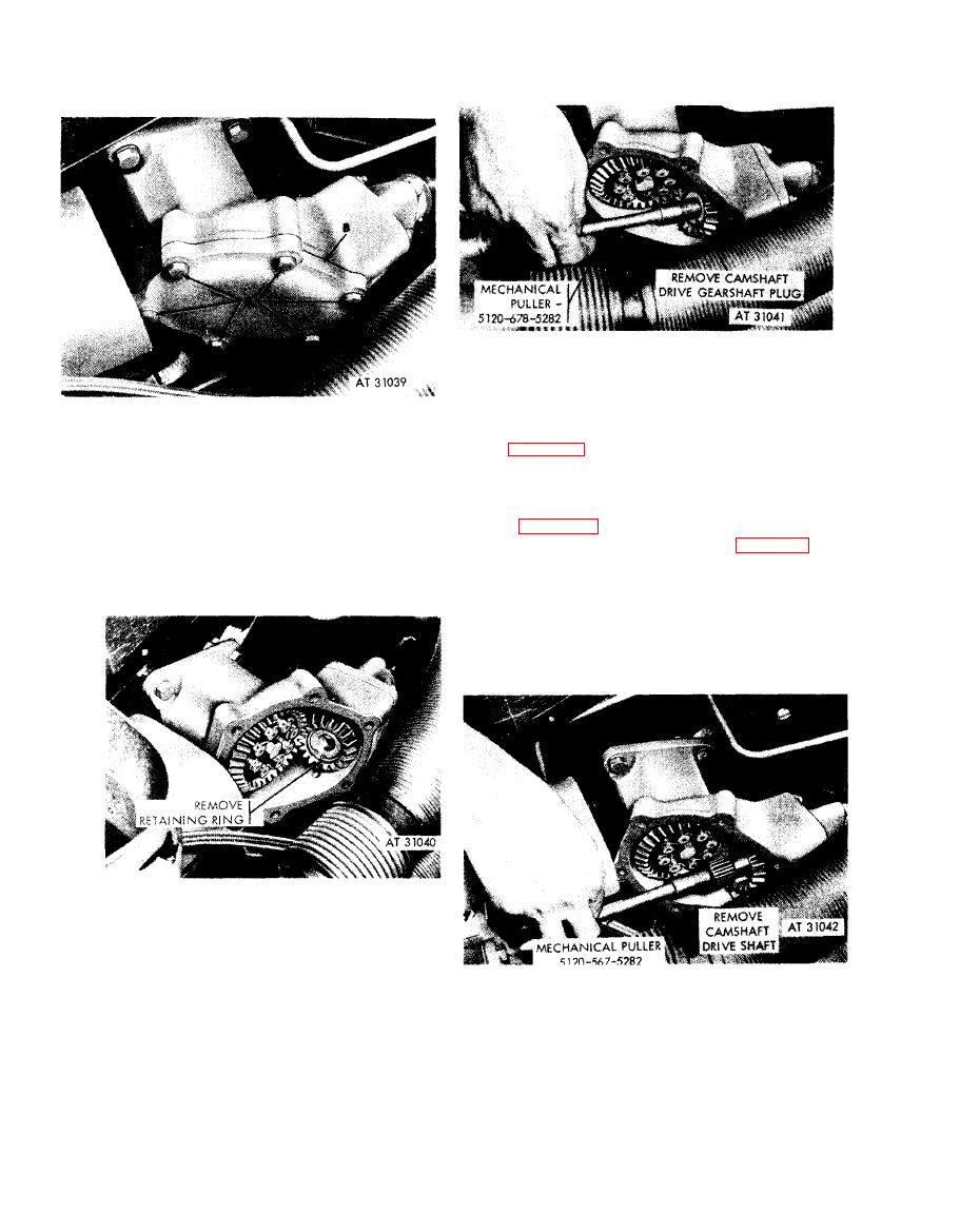 shaft drive gearshaft plug using mechanical
p u l l e r - 5120-678-5282.
d. Special Timing Instructions. W i t h
Remove
cylinder 6R intake valve set at the just closing
1. Remove six bolts (A), lock washers, and flat washers
p o i n t (fig. 4-195) turn flywheel approximately
attaching camshaft gear housing cover.
1/8 of a turn (or 45 degrees) clockwise (viewed at
2. Remove cover and gasket (B). Discard gasket.
Install
flywheel end) to remove backlash in g-ear train ;
1. Position new gasket (B) on camshaft gear housing.
then turn flywheel counterclockwise until timing
Install camshaft gear housing cover.
mark (fig. 4-196) is alined with the timing
2. Install six bolts (A), lock washers, and flat washers
pointer. Install camshaft drive shaft (fig. 4-201),
securing cover.
m a t i n g splines of drive shaft with splines on
Figure 4-198. Removing or installing cam-
drive gearshaft and with splines on cam drive
shaft gear housing cover.
bevel gearshaft. When splines of drive shaft will
not enter splines of cam drive bevel gearshaft,
w i t h d r a w drive shaft and turn slightly before
again attempting insertion.
Figure 4-199. Removing or installing cam-
shaft drive gearshaft plug retaining ring.
shaft drive shaft using mechanical
p u l l e r - 5120-678-5282.
4-102
|
|
Privacy Statement - Press Release - Copyright Information. - Contact Us |
