 |
|||
|
|
|||
|
Page Title:
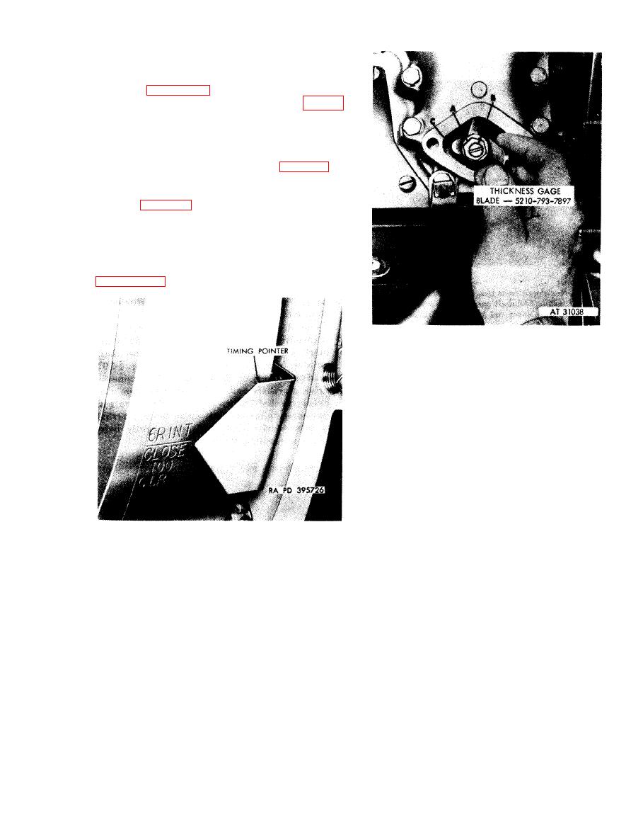
Figure 4-196. Flywheel timing marks a lined with pointer for valve timing-right bank of cylinders. |
|
||
| ||||||||||
|
|
 b. Positioning Camshaft. Turn engine using
splined wrench - 5120-793-7895
until
valve
rocker arm roller is on base circle of camshaft as
shown in figure 4-73. Set number 6R and 6L
i n t a k e valve clearance to 0.100 inch (fig. 4-
197).
c. Checking Valve Timing. Turn flywheel
counterclockwise, viewed from rear, until pad on
valve adjusting screw is just free of the valve
stem (intake valve has just closed) (fig. 4-195).
In this position the fly-wheel mark "6R INT
CLOSE 0.100 CLR" should be alined with
pointer (fig. 4-196). If flywheel marks are not
alined with pointer within inch at the time the
adjusting screw pad becomes free of valve stem it
will be necessary to remove camshaft drive shaft
and reset valve timing. Valve timing may be reset
following the instructions that accompany
1. Loosen timing adjusting screw lock nut (A).
2. Turn valve adjusting screw (B) and set valve
clearance to 0.100 inch.
3. Gage (C) must move through clearance with a slight
drag. Tighten lock nut after setting clearance. Check
clearance to make certain setting has not changed.
for cylinder 6R using thickness gage
blade-5120-793-7897.
Figure 4-196. Flywheel timing marks a lined
with pointer for valve timing-right bank
of cylinders.
4-101
|
|
Privacy Statement - Press Release - Copyright Information. - Contact Us |
