 |
|||
|
|
|||
|
Page Title:
Figure 4-193. Removing or installing oil cooler end shroud. |
|
||
| ||||||||||
|
|
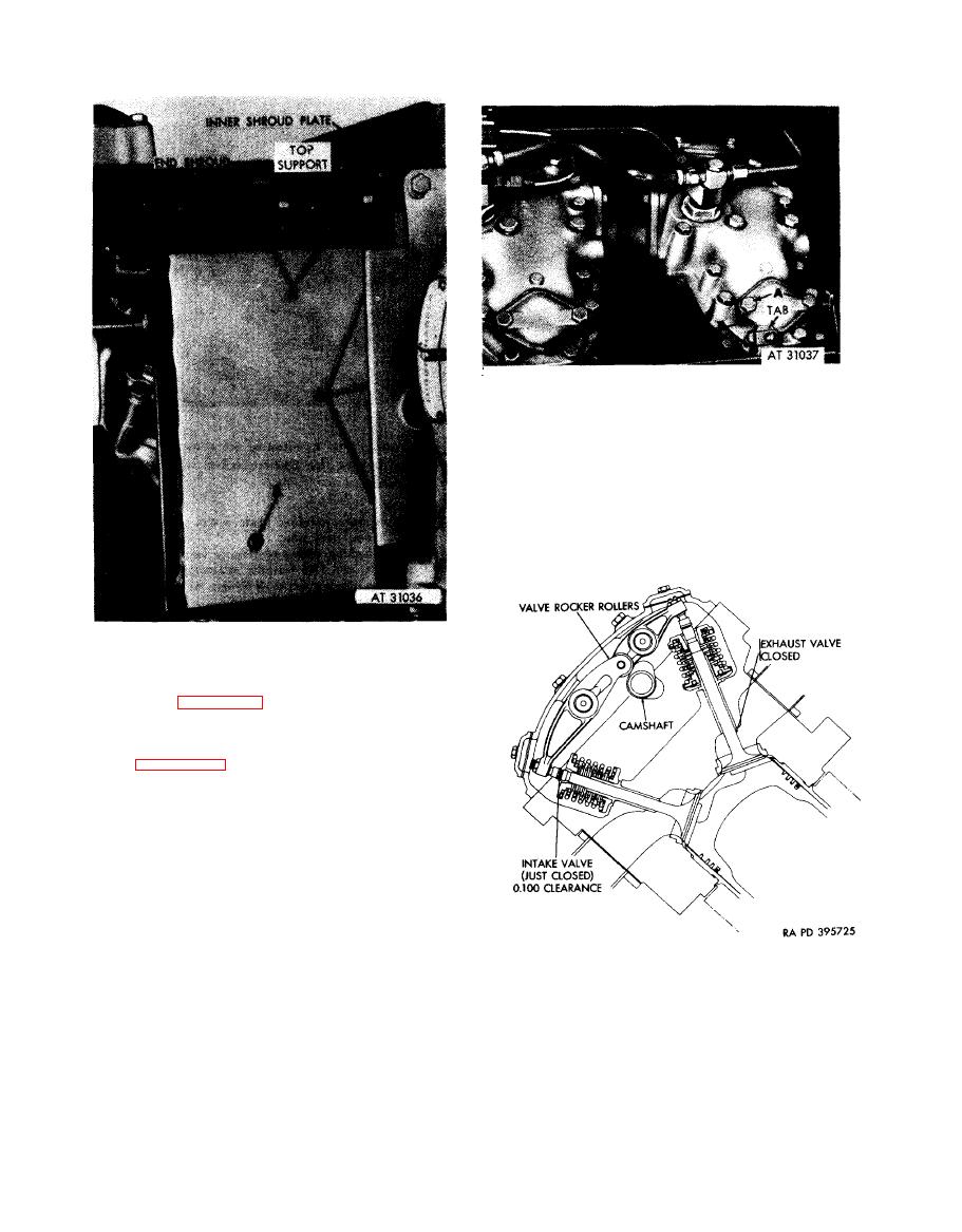 Remove
1. Remove two bolts (A) and flat washers attaching
intake valve adjusting screw cover plate.
2. Remove cover plate and gasket (B). Discard gasket.
Install
1. Position new gasket (B) on cylinder and install intake
valve adjusting screw cover plate.
2. Install two bolts (A) and flat washers securing cover
plate.
Figure 4-194. Removing or installing intake
valve cover plate.
Remove
1. Remove three screws (AI attaching end shroud to top
support and to tab on cylinder head.
2. Refer to figure 4-147 for removal of three screws (B)
attaching shroud to inner shroud plate. Remove shroud.
Iustall
1. Position end shroud with inner shroud plate and refer
to figure 4-147 for installation of three screws (B)
securing shroud to shroud plate.
2. Install three screws (A) attaching shroud to top
support and to tab on cylinder head.
Figure 4-193. Removing or installing oil
cooler end shroud.
showing position of camshaft lobes for
valve timing.
4-100
|
|
Privacy Statement - Press Release - Copyright Information. - Contact Us |
