 |
|||
|
|
|||
|
|
|||
| ||||||||||
|
|
 TM 9-2520-249-34&P
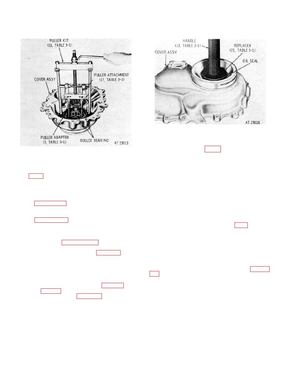
Figure 7-49. Installing output oil seal into end cover
assembly.
Figure 7-48. Removing roller bearing from end cover
new replacement part. Press the sleeve onto the cover,
beveled edge side first, until it is firmly seated against
assembly.
the cover.
c. If reduction drive and driven gear roller
e. Do not remove two screw thread inserts
bearings (69 and 85) were removed, install new
(83, FO-7) and two staking pins (84), unless
replacement parts. Chill the bearings in dry ice for 4
replacement of parts is necessary.
If necessary,
hours and heat the housing to 3500 F before installation.
remove the inserts and pins.
Make certain the bearings are fully seated when
installed.
7-124. Cleaning
NOTE
Refer to paragraph 5-2 for cleaning recommendations.
The cutout on the bearing race must
be indexed with the retaining plate
7-125. Inspection and Repair
location in the cover.
Refer to paragraph 5 3 for general inspection and repair
recommendations.
lockwasher (87) and bolt (88). Make certain the tab of
the lockwasher that is bent at right angle is inserted in
7-126. Repair Standards
the hole of the retaining plate. Bend the remaining two
a. Refer to paragraph 5 4 for explanation of
tabs against the flat sides of the bolt head.
repair standards.
e. If two screw thread inserts (83) and staking
b. Refer to repair standards (table 7-18).
pins (84) were removed, install new replacement parts
as follows: Select inserts for 0.002-inch tight to 0.002-
7-127. Assembly
inch loose fit. Install to the dimension given in figure 7-
(FO -7)
thread of the insert, and a sleeve with an outside
a. If oil seal (78) was removed, install a new
diameter smaller than the outside diameter of the insert,
replacement part. Using replacer (21, table 3-1) and
to install the inserts. The bolt should project through the
handle (13, table 3-1), press or drive the oil seal, spring
sleeve 1 1/4-inch for the 3/8-16 volts.
side first, into the end cover (figure 7-49).
7-41
|
|
Privacy Statement - Press Release - Copyright Information. - Contact Us |
