 |
|||
|
|
|||
|
Page Title:
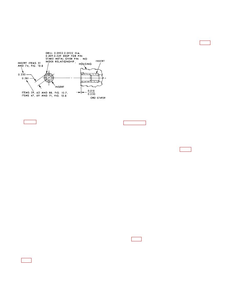
Figure 7-47. Dimensions for installing screw thread inserts and insert staking pins. |
|
||
| ||||||||||
|
|
 TM 9-2520-249-34& P
into the hole of the retaining plate. Bend the remaining
outside diameter smaller than the outside diameter of
two tabs against the flat sides of the bolt head.
the insert. to install the inserts. The bolt should project
(11) Install three output clutch sleeve bolts
through the sleeve one inch for the 5/16-18 thread bolts
(57) and three flat washers (58).
and one and one-quarter inch for the 3/8-16 thread
bolts.
(1) If the brake and steer coolant pressure
retaining valve assembly, items (48 through 51), were
removed, install new replacement parts. Install valve
seat (51) first, flat side down, into housing (55), pressing
the seat until it is firmly seated in the housing. Install
pressure retaining valve (50), convex side first, into
housing (55). Install pressure retaining spring (49).
Install spring guide (48) through spring (49), valve (50)
and seat (51) into the housing. Press the spring guide
into the housing until the top of the head is 0.450 inch
below the surface adjacent to the valve bore in housing
(55).
(2) If roll pin (54) was removed, install a
Figure 7-47. Dimensions for installing screw thread
new replacement. Press the pin to bottom in the hole.
inserts and insert staking pins.
(3) If screw thread inserts (53 and 56) and
staking pins (52 and 57) were removed, install new
(4) If three output pump needle bearings
replacement parts. Install to the dimensions given in
(70, FO-8) were removed, install three new
replacements. Press them flush with to 0. inch below,
inner thread of the insert, and a sleeve with an outside
the surface of housing (63).
diameter smaller than the outside diameter of the insert,
(5) If the brake and steer coolant pressure
to install the inserts. The bolt should project through the
retaining valve assembly, items (76 through 79), were
sleeve 1 inch for the 5/16 18 inch thread bolts and 1 1/4-
removed, install new replacement parts. Install valve
inch for the 3/816 thread bolts.
seat (76) first, flat side down, into housing (63), pressing
(4) If plugs (59, FO-7) were removed,
the seat until it is firmly seated in the housing. Install
install them.
pressure retaining valve (77), convex side first, in
(5) If two dowel pins (58) were removed,
housing (63). Install pressure retaining spring (78).
install new replacement parts. Press the pins to 0.300
Install spring guide (79) through spring (78), valve (77),
inch above the surface of housing (55).
and seat (76) into the housing. Press the spring guide
(6) If three plugs (60) were removed,
into the housing until the top of the head is 0.450 inch
install them.
below the surface adjacent to the valve bore in housing
(7) If reduction drive and driven gear
(63).
roller bearings (63 and 95) were removed, install new
(6) If plug (80) was removed, install it.
replacements. Chill the bearings in dry ice for 4 hours
(7) If roll pin (81) was removed, install a
and heat the housing to 3500 F before installation.
new replacement. Press the pin to bottom in the hole.
Make certain the bearings are fully seated when
(8) If the reduction drive and driven gear
installed.
roller bearings (21 and 36) were removed, install new
replacements. Chill the bearings in dry ice for 4 hours
NOTE
and heat the housing to 3500 F before installation.
The cutout on the bearing race must be
Make certain the bearings are fully seated when
indexed with the retaining plate location in
installed.
the housing.
NOTE
(8) Install output clutch sl eeve assembly
The cutout on the bearing race should be
(41, FO-7) with two sealrings (40). Retain the sealrings
indexed with the retaining plate location in the
with oil-soluble grease.
housing.
(9) Install retaining plate (94) with tab
lockwasher (93) and bolt (92). Make certain the tab of
(9) Install output clutch sleeve assembly
the washer that is bent at a right angle is inserted in the
(88, FO-8) with two sealrings (91). Retain the sealrings
hole in the retaining plate. Bend the remaining two tabs
with oil-soluble grease.
against the flat sides of the bolt head.
(10) Install retaining plate (56) with tab
(10) Install five output clutch sleeve bolts
lockwasher (55) and bolt (54). Make certain the tab of
(62) and five flat washers (61).
the lockwasher that is bent at a right angle is inserted
7-39
|
|
Privacy Statement - Press Release - Copyright Information. - Contact Us |
