 |
|||
|
|
|||
|
Page Title:
Section XXII. RIGHT OUTPUT END COVER ASSEMBLY AND SPEEDOMETER DRIVE COVER-REPAIR |
|
||
| ||||||||||
|
|
 TM 9-2520-249-34&P
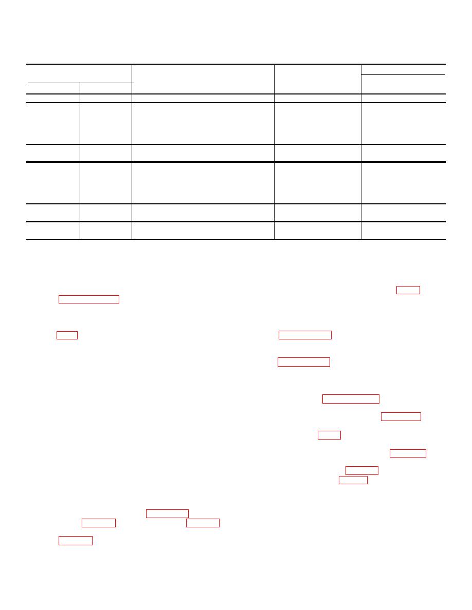
Table 7-18. Repair Standards Left Output End Cover)
Wear limit
Reference
Size and fit
DS/GS
Foldout
Item
Point of measurement
of new parts
maintenance
7
64a
Outside diameter at bearing surface of gear 3.7518 to 3.7528
7
69a
Outside diameter of bearing .................
5.5133 to 5.5141
*
7
81a
Inside diameter at bearing surface of cover 5.5106 to 5.5118
5.5123
7
69a,
Fit of bearing in cover ...........................
0.0015T to 0.0035T
81a
7
80a
Outside diameter of sleeve (installed) ...
7.999 to 8.003
7.990
7
81b
Inside diameter at bearing surface of cover 5.5106 to 5.5118
5.5123
7
85a,
Outside diameter of bearing .................
5.5133 to 5.5141
*
7
81 b.
Fit of bearing in cover ..........................
0.0015T to 0.0035T
85a
7
90a
Outside diameter at bearing surface of gear 3.7518 to 3.7528
*
7
90b
Outside diameter at lip seal surface of gear 3.5000 to 3.5005
3.4980
*Replace when worn beyond new dimensions.
Section XXII. RIGHT OUTPUT END COVER ASSEMBLY AND
SPEEDOMETER DRIVE COVER-REPAIR
7-128. Description
speedometer drive cover (4), unless replacement is
Refer to paragraph 2-26 for description of the right
necessary. If necessary, remove the oil seal.
output end cover assembly.
7-130. Cleaning
7-129. Disassembly
Refer to paragraph 5-2 for cleaning recommendations.
a. Do not remove oil seal (53) from output
end cover (46) unless replacement is necessary. If
7-131. Inspection and Repair
necessary, remove the seal.
Refer to paragraph 5 3 for general inspection and repair
b. Do not remove sleeve (49) from output end
recommendations.
cover (46) unless replacement is necessary.
If
necessary, remove the sleeve.
7-132. Repair Standards
c. Do not remove two speedometer drive
cover mounting pad dowel pins (50) unless replacement
repair standards.
is necessary. If necessary, remove the dowel pins.
d. Do not remove four screw thread inserts
(51) and four staking pins 152) unless replacement is
necessary. Do not remove two screw thread inserts (47)
a. If oil seal (53) was removed, install a new
and two staking pins (48) unless replacement is
replacement part. Using replacer (21, table 3-1) and
necessary. If necessary, remove the inserts and pins.
handle (13, table 3 1), press or drive the oil seal, spring
e. Do not remove reduction drive and driven
side first, into the end cover fig. 7-49).
gear roller bearing (15 and 40) from output end cover
(46), unless replacement is necessary. If necessary,
new replacement part. Press the sleeve onto the cover,
flatten tab lockwasher (42) and remove bolt (41), tab
beveled edge first. until firmly seated against the cover.
lockwasher (42) and retaining plate (43).
c. If two speedometer drive cover mounting
f.
Using adapter (3, table 3-1), puller
pad dowel pins (50) were removed, install new
attachment (17, table 3-1), and puller kit (18, table 3-1),
replacement parts. Press them into the mounting pad
remove the reduction drive and driven gear roller
so that they project 0.220 from the face of the pad.
bearings (fig. 7-48).
d. If four screw thread inserts (51) and four
7-42
|
|
Privacy Statement - Press Release - Copyright Information. - Contact Us |
