 |
|||
|
|
|||
|
|
|||
| ||||||||||
|
|
 TM 9-2520-246-34
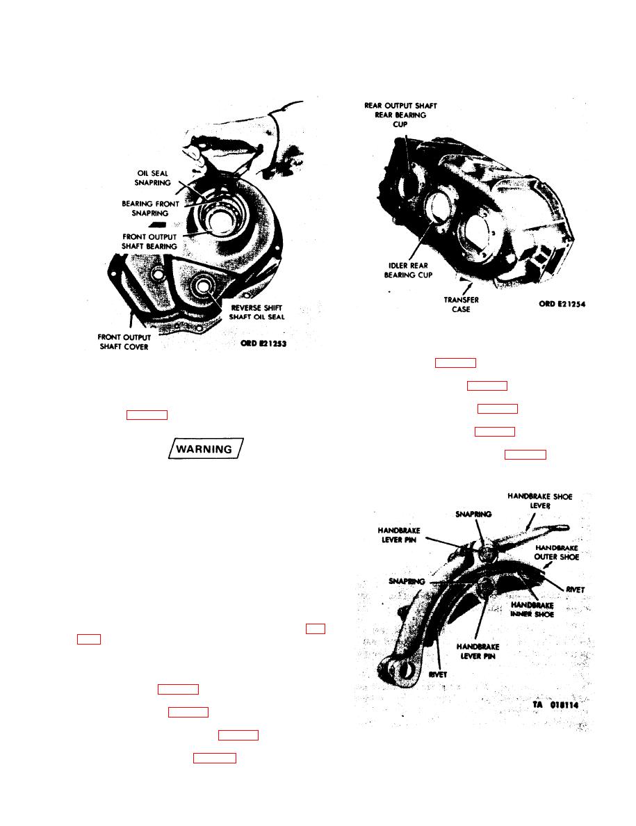
Figure 4-44. Transfer Case -- Disassembly.
Figure 4-43. Front Output Shaft Cover --
Disassembly.
(3) Remove the handbrake shoe lever and lever
pins. (See fig. 4-45.)
Replacement brakeshoes must be drilled for
rivet holes. Be sure to wear a mask to
prevent asbestos dust particles from
entering the lungs. Drilling must be done in
a well-ventilated area away from
unprotected personnel. Eyeglasses must
also be worn during drilling operation.
Failure to observe these precautions may
result in injury to personnel.
(4) Remove the 16 rivets securing the inner and
outer brakeshoes to the handbrake assembly. (See fig.
4-24. Assembly of Subassemblies.
Figure 4-45. Handbrake Shoe -- Disassembly.
4-29
|
|
Privacy Statement - Press Release - Copyright Information. - Contact Us |
