 |
|||
|
|
|||
|
|
|||
| ||||||||||
|
|
 TM 9-2520-246-34
h. Transfer Case.
NOTE
When pressing bearing cups back in
transfer case, be sure that the bearing cups
are not cocked, to avoid damage to the
bearing cups and transfer case which may
result.
Press the idler shaft rear bearing cup and rear
output shaft rear bearing cup from the transfer case
Refer to table 2, items 5 and 6.
Figure 4-41. Transfer Case Cover -- Disassembly.
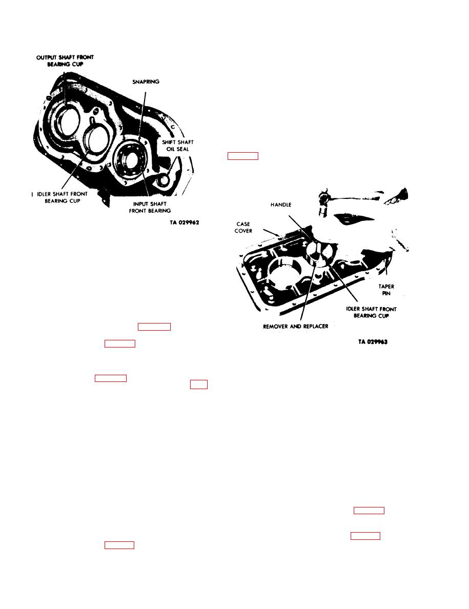
(2) Remote the input shaft front bearing
snapring from the input shaft front bearing.
(3) Using a suitable tool, remove the shift shaft
oil seal from the cover.
(4) Remove the idler-shaft front bearing cup by
removing the bearing cup snapring. Using a suitable
remover and replacer with handle (table 2-1, items 5
and 6), drive the idler-shaft front bearing cup from the
transfer case cover. (See fig. 4-42.)
Figure 4-42. Removing Idler Shaft Front
(5) Remove the rear output front bearing cup by
Bearing Cup.
removing the bearing cup snapring and, using suitable
remover and replacer, table 2-1, items 5 and 6, drive
i. Handbrake Shoe Assembly.
the bearing cup from the transfer case cover. (See fig.
4-22.)
NOTE
g. Front Output Shaft Cover.
Sometimes the handbrake shoes are not
NOTE
worn enough to warrant replacement. Use
good judgment in determining the condition
Coat the output shaft. shift shaft, and oil
of the shoes. Replace brake lining when
seals with grease. artillery and automotive
worn to 1/16 inch of the rivet heads. Worn
(GAA) MIL-G-10924, before assembling to
shoe linings can result in injury to
prevent damage to seals.
personnel and damage to the vehicle. Refer
to TM 9-2320-209-20/1 for wear limits and
(1) Remove the output shaft oil seal snapring
adjustments.
(fig . 4-43). Discard the oil seal. To remove the seal
(1) Remove the two snaprings holding the
from the cover, place in a press and exert pressure
handbrake lever pins in position. (See fig. 4-45.)
upon the front bearing thrust washer.
(2) Remove the two slotted washers which hold
(2) Remove the reverse shift shaft oil seal, using a
the stabilizer spring in position. (See fig. 4-27.)
suitable tool, and drive the shift shaft seal from the
Remove the brakeshoe stabilizer spring and pin.
output shaft cover. (See fig. 4-43.).
4-28
|
|
Privacy Statement - Press Release - Copyright Information. - Contact Us |
