 |
|||
|
|
|||
|
Page Title:
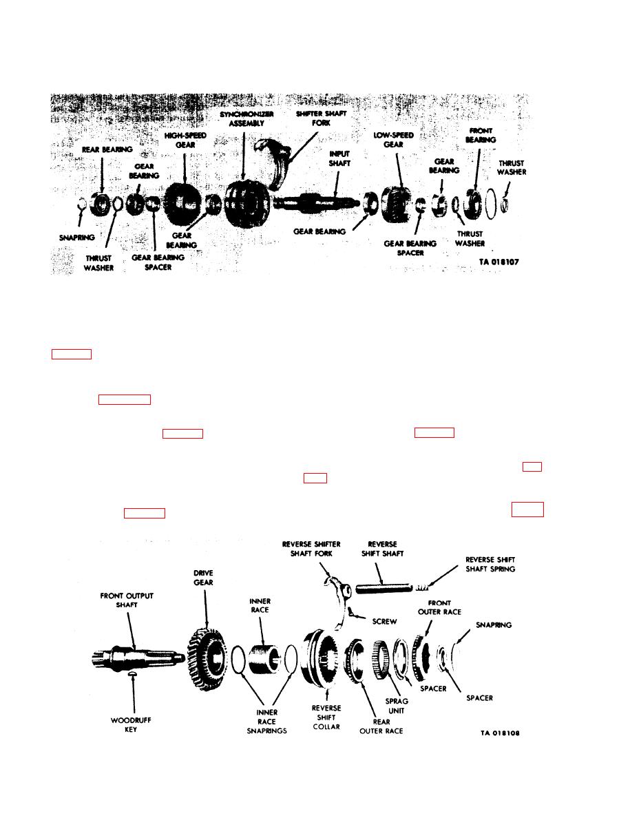
Figure 4-38. Input Shaft Disassembly -- Exploded View. |
|
||
| ||||||||||
|
|
 TM 9-2520-246-34
Figure 4-38. Input Shaft Disassembly -- Exploded View.
d. Front Output Shaft.
(3) Place the high-speed gear in a press and press
high-speed gear ball bearings and high-speed gear
NOTE
bearing spacer from the bore of the high-speed gear.
(See fig. 4-38.) Apply pressure to the inner race of the
Before installing the inner race and shaft
bearing only.
drive gear onto the shaft, coat the front
output shaft with white lead pigment, Fed
(4) Slide synchronizer assembly from the input
Spec TT-W-261C.
shaft. (See fig. 4-38.)
(1) Remove the reverse shifter shaft fork from the
(5) Place the input shaft assembly in an arbor
reverse shift collar. (See fig. 4-39.)
press, front bearing up. (See fig. 4-38.) Place support
bars beneath the low-speed gear, and press the low-
(2) Aline both of the outer races and slip the
speed gear, gear bearing, thrust washer, and front
reverse shift collar from the shaft assembly. (See fig.
bearing from the shaft.
(6) Place the low-speed gear in a press and press
(3) Remove the snapring and spacer and slip the
low-speed gear bearings, and gear bearing spacer from
front outer race from the shaft assembly. (See fig. 4-
low-speed gear. (See fig. 4-38.) Apply pressure to the
39.)
inner race of the bearing only.
Figure 4-39. Front Output Shaft Disassembly -- Exploded View.
4-26
|
|
Privacy Statement - Press Release - Copyright Information. - Contact Us |
