 |
|||
|
|
|||
|
Page Title:
SECTION III. INSPECTION AND SERVICING |
|
||
| ||||||||||
|
|
 TM 55-4940-353-13&P
SECTION III. INSPECTION AND SERVICING
3-3
Daily Inspection. The pressure gages and the
air connection must be disconnected and the top cover
sight gage on the Hose Tester (7, 12, 15 & 16, figure 2-
of the reservoir removed. If replacement of the filter
element is required, the gaskets which seal the top and
damage repaired. The air filter (2) should be checked
bottom of the element must also be replaced.
for contamination. If necessary, clear the air filter
through the bottom bleed valve. Check the oil level in
b. Pressure Cages (7, 15 & 16). Remove the
the air lubricator (8) and if less than one-quarter full, fill
gages from the Hose Tester, and using a master gage to
with SAE-10 oil. Check the oil level in the reservoir (5)
obtain a known pressure, apply a pressure equal to
through sight gage (20) and replenish if necessary.
approximately half scale to each gage. If a gage
Check the pump and fittings for evidence of external
indication is incorrect remove the glass cover and reset
leakage and repair as required.
the pointer for the correct value. Gage accuracy is + 3
percent of full scale.
3-4.
Periodic Inspection. The design and nature of
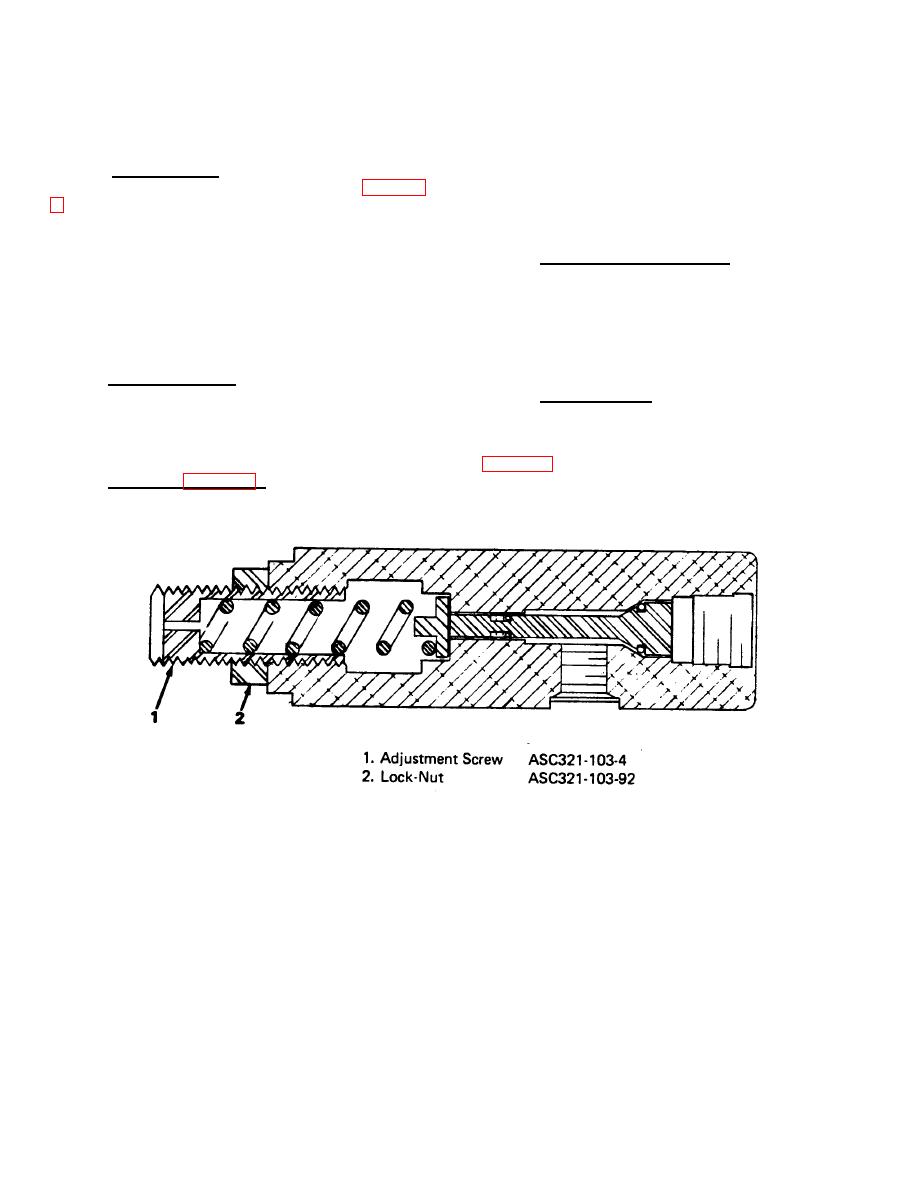
c. Gage Saver (17). Apply a known pressure, as
the Model 321 Hose Tester is such that a periodic
inspection need only be accomplished at six-month
read on oil pressure gage (16), to the unit and note the
intervals. At this time the following components of the
pressure at which it actuates. This pressure should be
unit should be checked:
2800 + 100 psig. If adjustment is necessary, refer to
adjustment screw (1) clockwise to increase the setting;
a. Oil Filter (6, figure 2-1). Check the oil filter for
contamination. To gain access to the oil filter, the shop
counterclockwise to decrease.
Figure 3-1. Gage Saver Adjustment
3-2
|
|
Privacy Statement - Press Release - Copyright Information. - Contact Us |
