 |
|||
|
|
|||
|
Page Title:
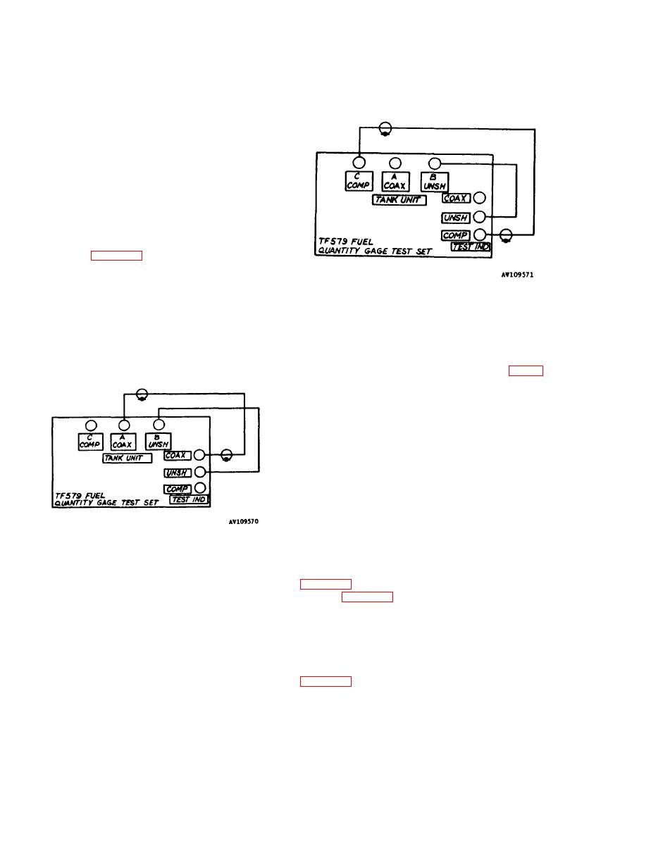
Figure 4-1. Setup for Checking TEST IND TEST Circuits, COAX- UNSH. |
|
||
| ||||||||||
|
|
 TM 55-4920-325-14&P
(200 pF step) (28) to 200, 400, 600, and 800 in
succession. Set Capacitance RANGE SELECTOR
switch (7) as required and check that CAPAC-
ITANCE INDICATOR (6) reads 230 5 pF, 430
6,5 pF, 630 9.0 pF, and 830 12.0 pF, re-
spectively.
i. Set PROBE MMF range selector switch
(200 pF step) (28) to OFF and (1000 pF step) (29)
to 1000, 2000, 3000, and 4000 in succession.
Check that CAPACITANCE INDICATOR (6) reads
1030225 pF, 2030 32.5 pF, 3030 45.0 pF, and
4030 60.0 pF. Record CAPACITANCE INDl-
CATOR (6) reading with PROBE MMF range se-
lector switch (1000 pF step) (29) set to 4000.
j. Connect appropriate test cables to test set
as shown in figure 4-1.
Figure 4-2. Setup for Checking TEST IND TEST
Circuits, COMP-UNSH.
4-2.
0. Set FUNCTION SELECTOR switch (25) to
TANK UNIT TEST-COMP and check that CAPAC-
ITANCE INDICATOR (6) reads 100 pF.
p. Set Megohmmeter RANGE SELECTOR
switch (17) to ZERO CAL and check that ME-
GOHMMETER indicator (14) reads exactly ZERO
megohms. Refer to 2-8f for calibration if neces-
sary.
q. Set Megohmmeter RANGE SELECTOR
switch (17) to MIDSCALE CAL and check that
MEGOHMMETER indicator (14) reads exactly 1
megohm (MIDSCALE). Refer to 2-8f for cal-
Figure 4-1. Setup for Checking TEST IND TEST
ibration if necessary.
Circuits, COAX- UNSH.
shown in figure 4-3.
k. Set FUNCTION SELECTOR switch (25) to
TANK UNIT TEST-UNSH and check that CAPAC-
s. Set CAP-RES switch (13) to EXT RES, Me-
ITANCE INDICATOR (6) reads value recorded in
gohmmeter RANGE SELECTOR switch (17) to X1
step i above.
and check that MEGOHMMETER indicator (14)
reads 1 megohm.
/. Set FUNCTION SELECTOR switch (25) to
TEST IND COMP SET, release COMP 25-250
t. Substitute 10 megohm resistance standard
MMF control lock (23) and repeat step g above
using COMP 25-250 MMF control (22).
across EXT RES terminals (18) and set Me-
m. Adjust COMP 25-250 MMF control (22) for
gohmmeter RANGE SELECTOR switch (17) to
X10. Check that MEGOHMMETER indicator (14)
CAPACITOR INDICATOR (6) reading of 100 pF.
reads 10 megohms.
Disconnect test cables.
4-2
|
|
Privacy Statement - Press Release - Copyright Information. - Contact Us |
