 |
|||
|
|
|||
|
Page Title:
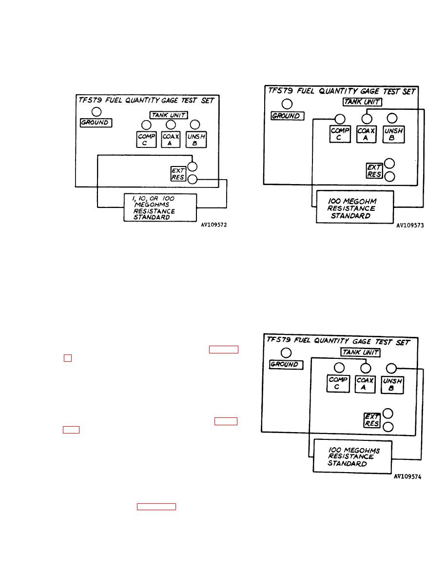
Figure 4-3. Setup for Checking Resistance Measuring Circuits Using EXT RES Terminals. |
|
||
| ||||||||||
|
|
 TM 55-4920-325-14&P
Figure 4-4. Setup for Checking Resistance Mea-
suring Circuits Using EXT RES Terminals.
suring Circuits using TANK UNIT COMP C and
COAX A Connectors.
u. Substitute 100 megohm resistance stan-
dard for 10 megohm resistance standard (table 1-
gohmmeter RANGE SELECTOR switch to X100.
Check that MEGOHMMETER indicator (14) reads
100 megohms. Disconnect 100 megohm re-
sistance standard.
v. Connect 100 megohm resistance standard
across TANK UNIT COMP C (10) and TANK
UNIT COAX A (11) connectors as shown in figure
GOHMS A-C A-B.
w . Check that MEGOHMMETER Indicator
(14) reads 1 megohm 0.125 inch of scale. Dis-
connect 100 megohm resistance standard.
x. Repeat step w above with 100 megohm re-
sistance standard connected across TANK UNIT
COAX A (11) and TANK UNIT UNSH B (12) con-
Figure 4-5. Setup for Checking Resistance Mea-
ectors as shown in figure 4-5. Disconnect 100
suring Circuits Using TANK UNIT COAX A and
megohm resistance standard.
UNSH B Connectors.
4-3
|
|
Privacy Statement - Press Release - Copyright Information. - Contact Us |
