 |
|||
|
|
|||
|
Page Title:
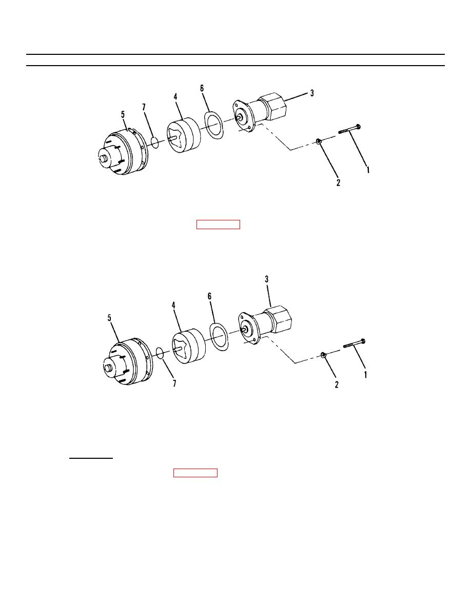
Figure 4-12.1. Hydraulic Brake Replacement. |
|
||
| ||||||||||
|
|
 TM55-1730-228-13&P
4-12. HYDRAULIC MOTOR, BRAKE AND DRIVE HUB ASSEMBLY- REPAIR (Continued)
4-12
Figure 4-12.1. Hydraulic Brake Replacement.
(p) Place new preformed packing (7, Figure 4-12.1) on face of brake assembly (4).
(q) Place new gasket (6) on face of drive motor (3).
(r) Assemble drive hub (5), brake assembly (4) and drive motor (3). Install two capscrews (1) and washers
(2). Tighten capscrews securely.
Figure 4-13. Drive Hub Replacement.
c. DRIVE HUB - REPAIR
(1) Disassembly:
(a) Remove two capscrews (1, Figure 4-13) and washers (2).
GO ON TO NEXT PAGE
4-40
|
|
Privacy Statement - Press Release - Copyright Information. - Contact Us |
