 |
|||
|
|
|||
|
Page Title:
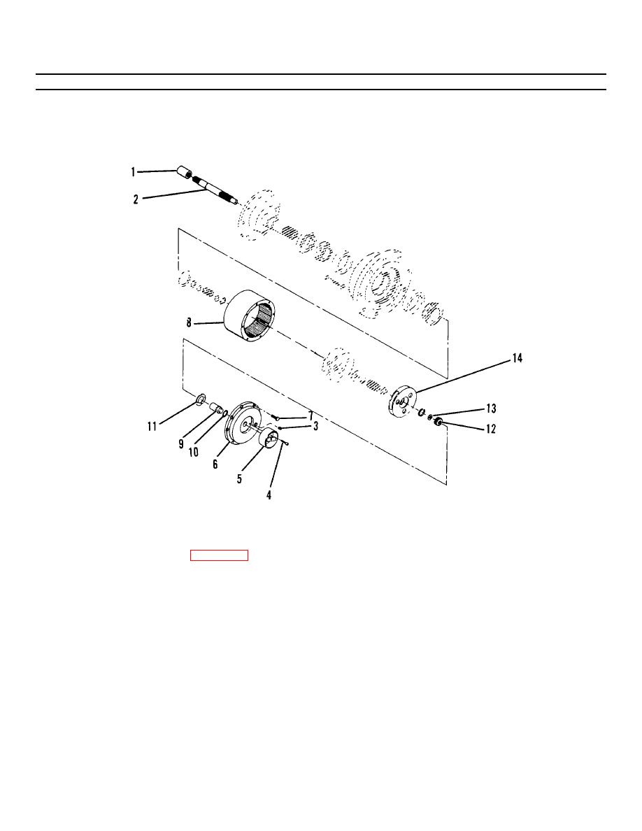
Figure 4-14. Drive Hub Assembly (Sheet 1 of 3). |
|
||
| ||||||||||
|
|
 TM55-1730-228-13&P
4-12. HYDRAULIC MOTOR, BRAKE AND DRIVE HUB ASSEMBLY- REPAIR (Continued)
4-12
(b) Remove drive motor assembly (3). Remove gas ket (6) and discard.
(c) Separate brake assembly (4) from drive hub (5). Remove preformed packing (7) and discard.
Figure 4-14. Drive Hub Assembly (Sheet 1 of 3).
(d) Slide coupling (1, Figure 4-14) off input shaft (2).
(e) Remove plug (3) and drain gear lube into a suitable container.
(f) Remove two socket head capscrews (4) securing lockout mechanism (5) to cover (6).
(g) Remove eight capscrews (7) securing cover (6) to ring gear (8). Tap cover with soft faced mallet and
remove.
(h) Remove disengage plunger (9), preformed packing (10) and thrust washer (11).
(i) Remove small sun gear (12) and thrust washer (13) from end of input shaft (2).
(j) Remove primary carrier assembly (14).
GO ON TO NEXT PAGE
4-41
|
|
Privacy Statement - Press Release - Copyright Information. - Contact Us |
