 |
|||
|
|
|||
|
Page Title:
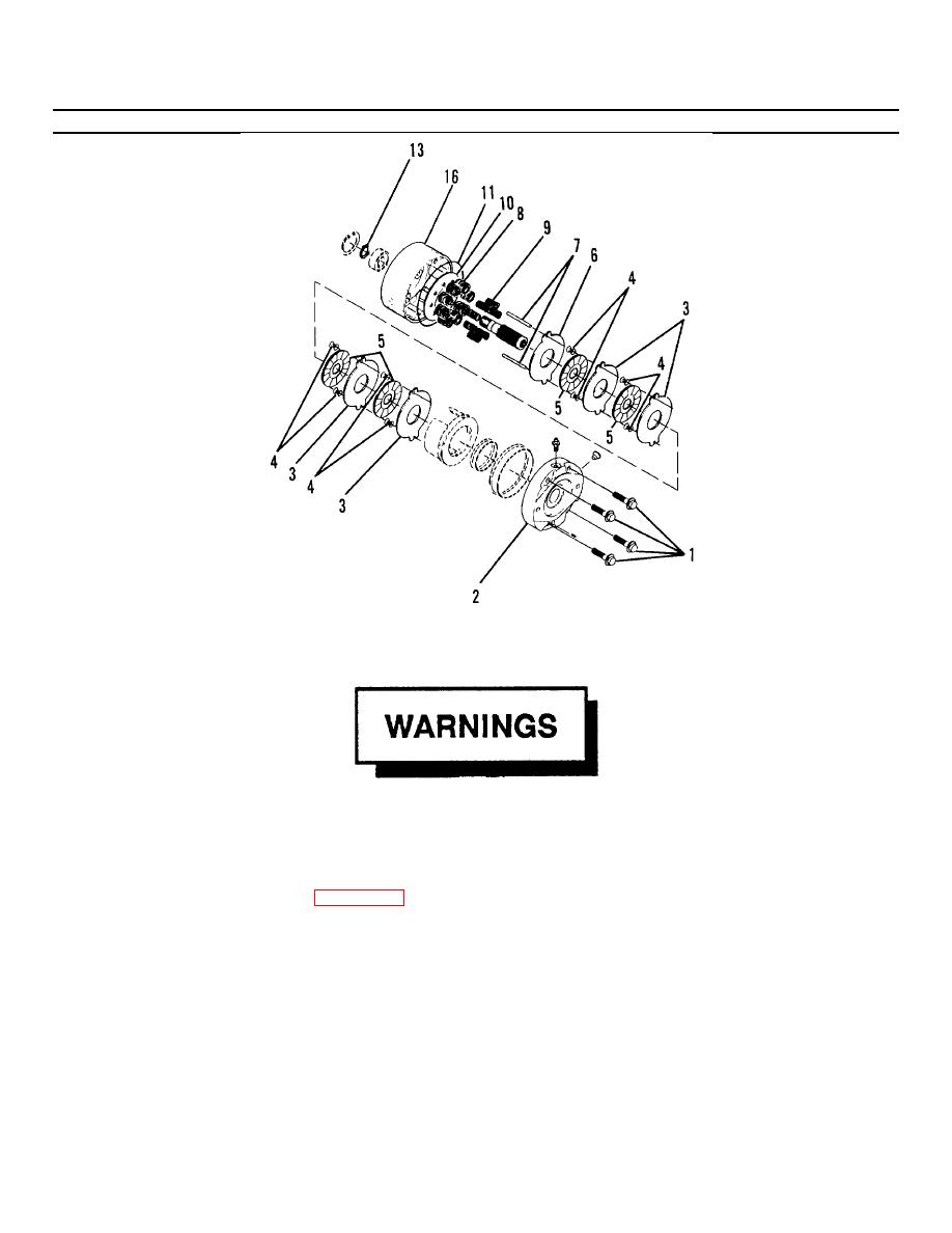
Figure 4-12. Hydraulic Brake Assembly (Sheet 1 of 2). |
|
||
| ||||||||||
|
|
 TM55-1730-228-13&P
4-12. HYDRAULIC MOTOR, BRAKE AND DRIVE HUB ASSEMBLY- REPAIR (Continued)
4-12
Figure 4-12. Hydraulic Brake Assembly (Sheet 1 of 2).
Brake assembly under spring pressure. Use extreme caution when disassembling the brake assembly. Failure to do so
may result in severe personal injury.
(f) Remove capscrews (1, Figure 4-12) alternately. Loosen each screw 3-4 turns and tap the housing lightly
with a soft faced mallet so that the face of the power plate comes up against the capscrew heads.
Repeat this procedure until the capscrews can be removed.
(g) Remove power plate (2), four stationary discs (3), eight springs (4), four rotating discs (5), primary disc
(6), two pins (7), eight springs (8), eight springs (9) and spring retainer (10).
(h) Remove preformed packing (11) from housing and discard.
(i) Remove retaining ring (13).
GO ON TO NEXT PAGE
4-37
|
|
Privacy Statement - Press Release - Copyright Information. - Contact Us |
