 |
|||
|
|
|||
|
Page Title:
ADJUSTING DRIVE CLUTCH PINION CLEARANCE |
|
||
| ||||||||||
|
|
 (5) Mark location of brushes, and, remove
d . Installation of Drive Housing. Refer to
brushes from holders. Remove commu-
tator end plate from armature. Remove
sandpaper,
and
clean
armature,
3 6 . ADJUSTING DRIVE CLUTCH PINION
b r u s h e s , a n d commutator end plate.
CLEARANCE
Sanding dust can be removed using com-
pressed air.
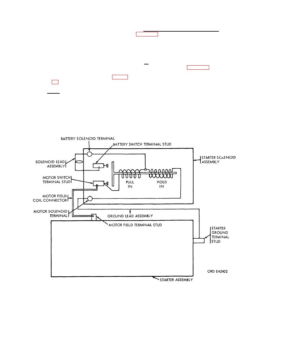
a . Check and adjust pinion clearance as de-
scribed below. Refer to figure 37 for schematic
(6) Install commutator end plate, brushes,
w i r i n g diagram of starter and solenoid con-
a r m a t u r e , brush leads and terminal
nections.
lead following steps 2 through 6, fig-
ure 34.
(1) Remove motor field coil connector from
the motor switch terminal stud.
N o t e . The armature shaft and splines
must be coated with grease (GL) before
(2) Remove ground lead assembly connect-
installation. Coat all exposed metal of
ing motor solenoid terminal and starter
s t a r t e r lead and terminals with vinyl
latex or equivalent.
ground terminal stud.
|
|
Privacy Statement - Press Release - Copyright Information. - Contact Us |