 |
|||
|
|
|||
|
|
|||
| ||||||||||
|
|
 TM 9- 2920- 232- 34&P / TO 38X14- 2- 32
-
-
-
- -
ASSEMBLY OF THE STARTER - CONTINUED
-
0010 00
Adjustment
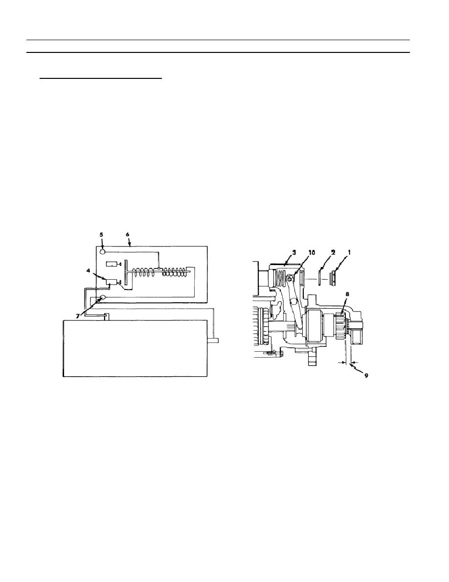
1. Adjustment of Drive Pinion Clearance.
a. Remove inspection plug (1) and gasket (2) from lever housing (3).
b. Connect 24--volt power to MTR (4) and S (5) terminals of solenoid assembly (6).
c.
Make a momentary connection between solenoid G terminal (7) and solenoid MTR terminal (4); drive (8) will
shift to engaged position and remain even though MTR connection is removed.
d. Manually push drive pinion (8) towards opposite end of the starter to eliminate backlash from measurement.
e. Using measuring tape, measure distance (9) of pinion face to machined surface of drive end housing as
shown.
f.
Turn adjustment nut (10) as necessary to obtain clearance measurement (9) of 21/64 to 25/64 inch.
g. Remove power supply connection and again connect electrical lead to G terminal of solenoid assembly.
Torque washer nut to 16--30 lb--in (1.8 to 3.4 Nm).
h. Apply a light coat of grease to gasket (2). Install gasket (2) and inspection plug (1) into lever housing (3).
Torque to 4--6 lb--ft (5.4 to 8.1 Nm).
END OF WORK PACKAGE
0010 00- 16
-
|
|
Privacy Statement - Press Release - Copyright Information. - Contact Us |