 |
|||
|
|
|||
|
Page Title:
Connect terminal end of field lead |
|
||
| ||||||||||
|
|
 TM 9- 2920- 224- 34&P
-
-
-
ASSEMBLY OF THE GENERATOR - CONTINUED
-
0010 00
f.
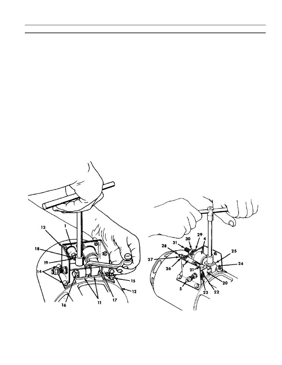
Ensure that both nonmetallic grommets (11) are installed on stator housing (12).
NOTE
Equivalent for washer bolts (14) will be installed on
generator 10889713 when guard is installed.
g. Apply sealer to mounting surface and position assembled parts of radio interference filter (13) on housing
(12). Install two washer bolts (14) for generators 8717421 or 11642898 only. Install two washer bolts (15) to
secure side of filter (13) opposite its ground terminal to housing (12) on all generators.
h. Connect terminal end of field lead (16) to lower terminal of capacitor assembly (1). Connect terminal end of
equalizer lead (17) to upper terminal of capacitor assembly (1). Install one flat washer (18) and one new
self--locking nut (19) on each terminal. Torque to 16--30 Ib--in (1.8 to 3.4 Nm).
i.
Connect the negative brush bus (20) (stamped "E") to ground lead (5) with machine bolt (21), one flat washer
(22), and one new self--locking nut (23). Install machine bolt (21), flat washer (22), and new self--locking nut
(23) to connect positive brush bus (24) (stamped "B") to flat terminal (25) of capacitor (4). Torque to 5--10 Ib--ft
(6.8 to 13.6 Nm).
j.
Install flat washer (26) and new self--locking nut (27) on each external terminal (28) of capacitor assembly (1).
Tighten nut finger tight.
k.
Install flat washer (29) and new self--locking nut (30) on terminal stud (31) of capacitor (4). Tighten nut finger
tight.
0010 00- 5
-
|
|
Privacy Statement - Press Release - Copyright Information. - Contact Us |