 |
|||
|
|
|||
|
Page Title:
Installation of Quill Shaft Assembly |
|
||
| ||||||||||
|
|
 TM 9-2910-226-34
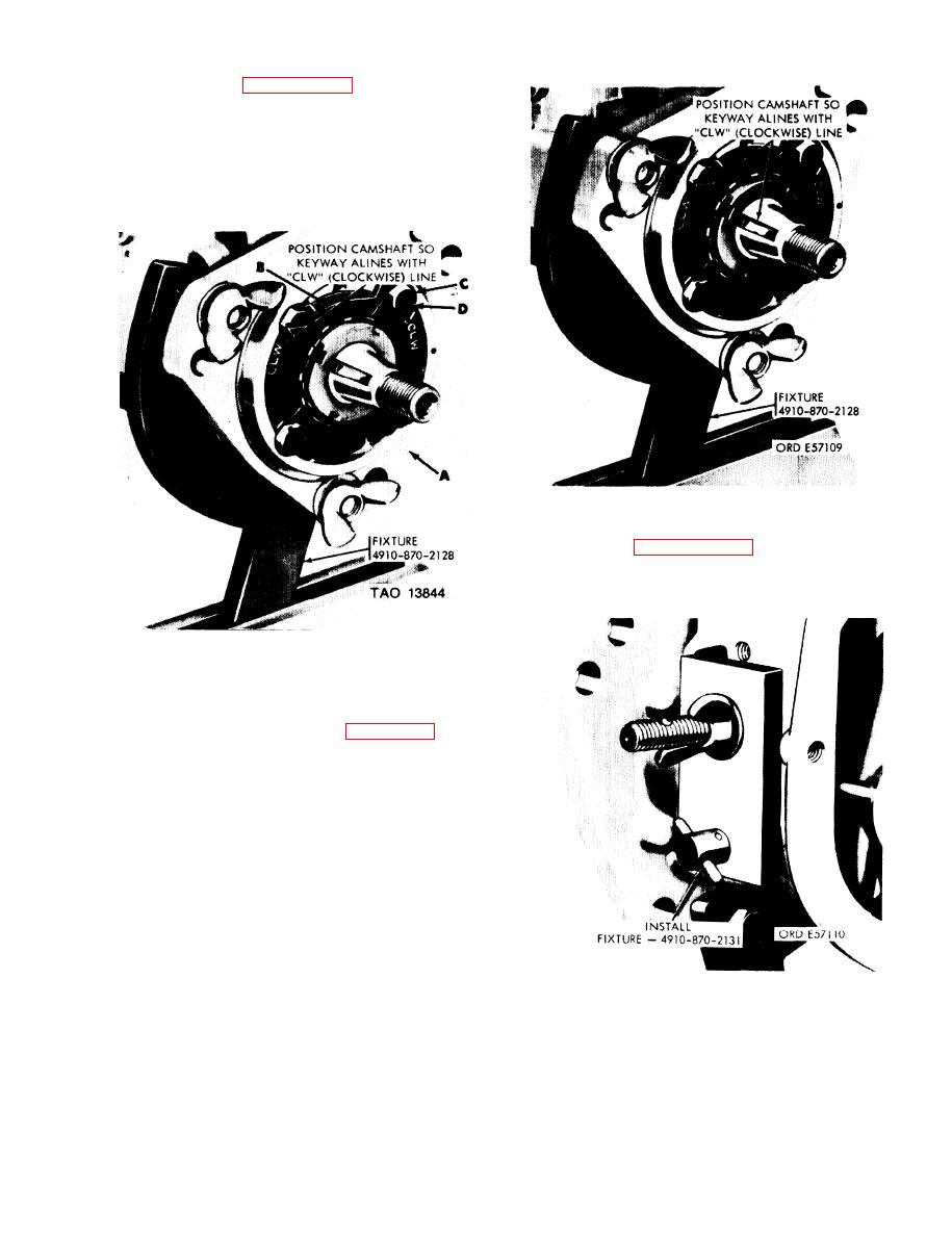
(2) Refer to figure 3-112. Install fixture --
4910-870-2128 on injection pump housing (A) and in-
stall fixture in a vise. Position bearing retaining plate
(B) so CLW (clockwise) line is as shown, Install four
lockwashers (C) and machine screws (D). Tighten
screws and bend tabs of lockwashers over screw heads
to secure screws.
Figure 3-113. Positioning camshaft prior to installing
quill shaft assembly.
4910-870-2131 as shown to lock camshaft and prevent
rotation
Figure 3-112. Installing bearing retaining plate using fixture.
3-38. Installation of Quill Shaft
Assembly
installing quill shaft assembly.
Figure 3-114. Locking camshaft to prevent rotation.
3-71
|
|
Privacy Statement - Press Release - Copyright Information. - Contact Us |
