 |
|||
|
|
|||
|
Page Title:
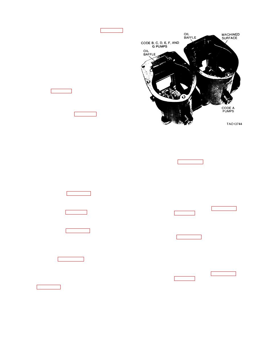
Figure 3-72. Identification of governor housings. |
|
||
| ||||||||||
|
|
 TM 9-2910-226-34
(5) Check sliding sleeve (B) against the limits
specified in the repair standards (para 3-60) and
replace the sleeve when it does not meet these
requirements. Inspect the bearing face of the sleeve
to determine the depth of any indentations. When
indentations exceed 0.008 -inch, replace the sliding
sleeve.
(6) Examine the operating shaft bearing (Z) for
burs, nicks, and scratches on the gasket surface and
hub diameter. Repair minor burs, nicks, and
scratches with a fine mill file or crocus cloth. Replace
the operating shaft bearing when any of these
conditions are excessive. Check the operating shaft
bearing against the limits specified in the repair
standards (para 3-60) and replace the bearing when it
does not meet these requirements.
(7) Inspect the operating shaft (FF) and shaft
spring plate (EE) for wear and replace any worn part
or parts. Check parts against the limits specified in
the repair standards (para 3-60) and replace parts
when they do not meet these requirements. Examine
the ends of the operating shaft spring (W) for wear
and indentations. When the spring ends are worn or
have indentations that exceed 0.004-inch, replace the
Figure 3-72. Identification of governor housings.
spring. Generally if the shaft is replaced, the bearing
NOTE
plate is also replaced.
Refer to (2) below for assembly instructions
(8) Inspect the smoke limit cam (C-6) for wear
on the fulcrum lever used on code A, B, C,
patterns and any other visible damage. Replace the
D, E, and F series pumps. Refer to (3) below
part when either condition exists.
for instructions on code G pumps.
(9) Inspect fuel control rod (C-2) and control rod
(2) Refer to figure 3-67. Code A pumps must
pin screw (C-5) for wear patterns and any other
have a fulcrum lever pivot pin dimension (X) of
visible damage. Replace parts when either condition
0.204. Code B, C, D, E, and F pumps must have a
exists.
fulcrum lever pivot pin dimension (X) of 0.165.
NOTE
Install setscrew (J). (Setscrew (J) is not used on code
Sub-paragraphs (10) and (11) below apply
C and D pumps. ) Assemble spacer (K) (spacer (K) is
only to code A injection pumps.
used only on code A pumps) and smoke limit cam
(10) Refer to figure 3-66. Inspect the operating
(H) on control rod pin screw (G) and install the
shaft torque link pivot pins (E) and shaft assembly
control rod pin screw on the fulcrum lever. Secure
(D) for wear and replace shaft assembly if any part is
with lock washer (F) and hex nut (E) after setting
worn, Check shaft against the limits specified in the
the smoke cam angle per table in figure 3-73. Use
repair standards (para 3-60).
improvised tool (figure 2-1 ) to set cam angle. Torque
NOTE
tighten hex nut (E) to 50-60 inch-pounds. Install
If operating shaft is replaced, replace shaft
spring (D) and washer (C) on control rod pin screw
bearing.
and install control rod (B). Secure with self-locking
(11) Refer to figure 3-66. Inspect pin slots, and
nut (A) torqued to 12 14 inch pounds.
stop pin on torque link (C) for wear, damage and
(3) Refer to figure 3-67. Code G pumps should
cracks. Replace torque link where showing wear or
have a fulcrum lever pivot pin dimension of 0.165.
damage.
Install setscrew (T) and hex nut (S). One or two
c. Assembly. Assemble the governor as follows:
threads of setscrew should extend beyond hex nut
NOTE
for preliminary adjustments. Assemble smoke limit
Refer to figure 3-72 for identification of
cam (U) on control rod pin screw (Q) and intall the
governor housings. All pumps use a pipe
control rod pin screw on the fulcrum lever. Secure
plug in the bottom of the governor housing
with lock washer (R) and hex nut (P) after setting
as shown.
the smoke cam angle per table in figure 3-73. Use
(1) The parts in the universal governor and
improvised tool (figure 2-1 ) to set cam angle. Torque
linkage repair kit 5702685 are listed and illustrated
tighten hex nut to 50-60 inch-pounds. Install fuel
in appendix B. The parts applicable to this governor
control rod (N), flat washer (M) and cotter pin (L).
and linkage must be used in repair of the governor.
3-49
|
|
Privacy Statement - Press Release - Copyright Information. - Contact Us |
