 |
|||
|
|
|||
|
Page Title:
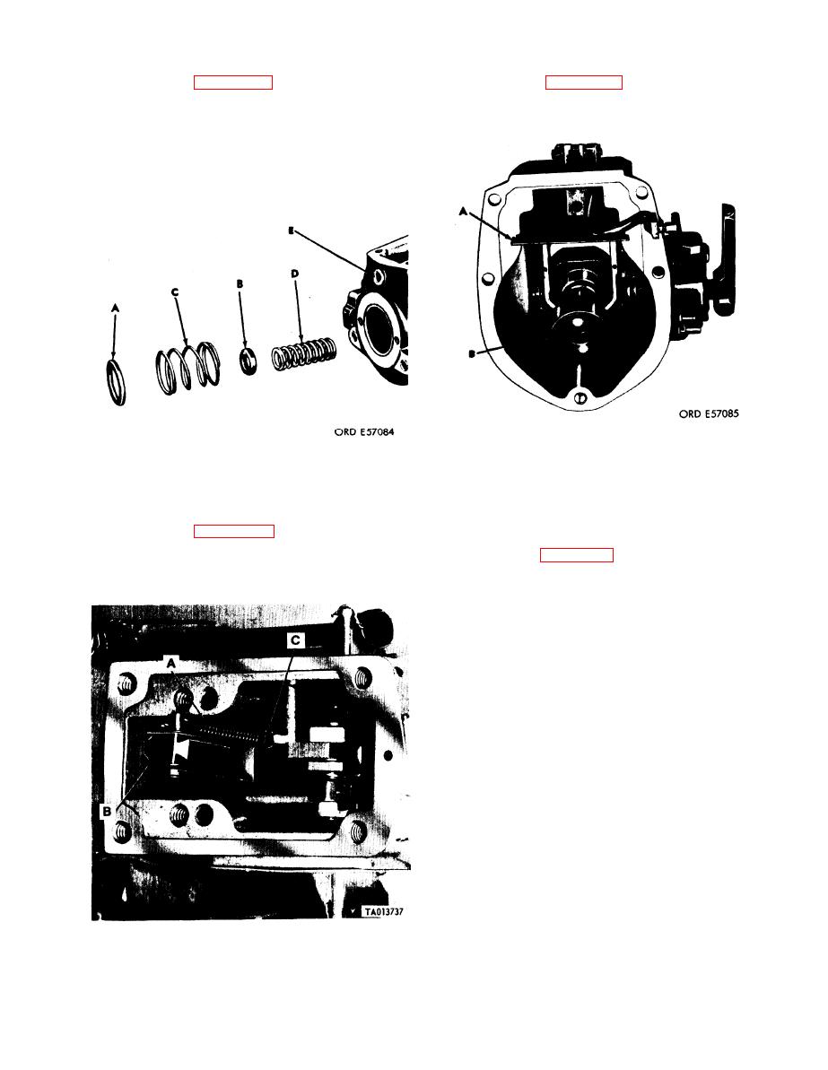
Figure 3-55. Removing inner and outer springs and spacers. |
|
||
| ||||||||||
|
|
 TM 9-2910-226-34
(4) Refer to figure 3-57. Remove oil baffle (A)
(2) Refer to figure 3-55. Remove outer spring
and sliding sleeve (B).
spacer (A), inner spring spacer (B), governor outer
spring (C), governor inner spring (D), and pipe plug
(E).
Figure 3-57. Removing oil baffle and sliding sleeve.
NOTE
Figure 3-55. Removing inner and outer springs and spacers.
The operating lever on code A pumps and
NOTE
early code G pumps is a one-piece lever; all
Paragraph (3) applies only to code A in-
others are two-piece. Discard all one-piece
jection pumps.
levers on early code G pumps and replace
(3) Refer to figure 3-56. Unhook torque link
with two-piece lever.
spring (A) from torque link (B) and oil baffle (C) and
(5) Refer to figure 3-58 or 3-59. Remove the lead
remove spring.
seal (A). Remove machine bolts (B), lockwashers (C)
and dust cover (D). Remove nut (E), lockwasher (F),
and clamping screw (G). Remove operating lever
(H).
Figure 3-56. Removing torque link spring (Code A pumps).
3-39
|
|
Privacy Statement - Press Release - Copyright Information. - Contact Us |
