 |
|||
|
|
|||
|
Page Title:
Removal of Fuel Control Unit Assembly |
|
||
| ||||||||||
|
|
 TM 9-2910-226-34
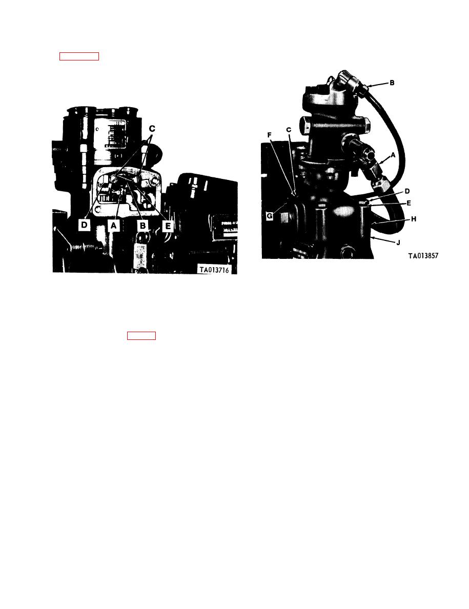
3-8. Removal of Fuel Control Unit Assembly. Refer
to figure 3-6. Remove retaining pin (A). Cut locking
wire (B) and remove two screws and lockwashers (C).
Remove control unit retainer (D) and fuel control
unit assembly (E).
Figure 3-7. Removing fuel density compensator
(early code F pumps).
Figure 3-6. Removing fuel control unit assembly.
b. Removal of Compensators.
3-9. Removal of Fuel Density Compensator
(1) Early code F injection pump. Refer to figure
Assembly and Governor Cover and Stop Plate and
3-7. Remove hose assembly (A) and tube (B) from
Bridge. a. General The fuel density compensator
tees and elbows. Remove and discard locking wire
assembly is mounted above the governor housing.
and seal (C). Remove four capscrews (D), lock-
A hose or tube (A, fig. 3-7) connects the density
washers (E), tamper proof cover (F) and spacers (G)
compensator to the hydraulic head and carries fuel
securing compensator to governor housing. Tap fuel
under pressure to the head. Excess or overflow fuel is
density compensator (H) with a soft hammer to
carried from the density compensator to the overflow
break gasket seal and remove fuel density com-
valve assembly by a tube (B).
3-3
|
|
Privacy Statement - Press Release - Copyright Information. - Contact Us |
