 |
|||
|
|
|||
|
Page Title:
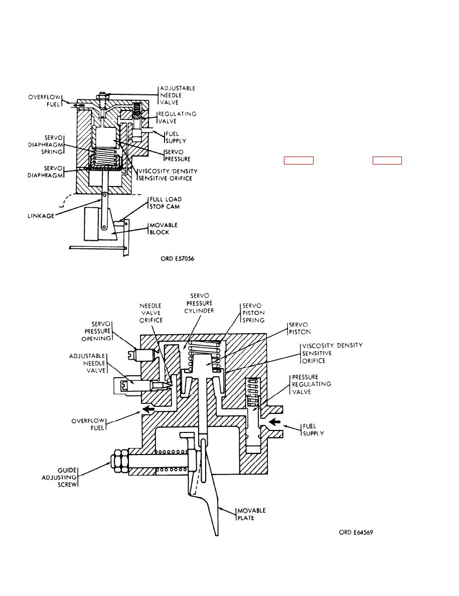
Figure 1-29. Fuel density compensator (code A, B, C, D and E) sectional view. |
|
||
| ||||||||||
|
|
 TM 9-2910-226-34
c. The fuel supply is admitted to a pressure
regulating valve where the supply pressure is
reduced to a constant regulated pressure over the
engine operating speed and load range. Fuel flows
through the first (viscosity/density sensitive) an-
nular orifice formed by a close fitting piston in a
cylinder. From the servo pressure cylinder the fuel
flows to the second orifice which is a sharp-edged,
adjustable needle valve. The two orifices working at
widely different restrictions to the flow of fuel form a
system sensitive to viscosity changes. The pressure
difference between the two orifices will change the
servo pressure in direct relationship to the viscosity
of the fuel flowing. The position of the spring-loaded
servo diaphragm (fig. 1-28) or servo piston (fig. 1-29)
is varied in accordance with these servo pressure
drops.
Figure 1-28. Fuel density compensator (early code F),
sectional view.
Figure 1-29. Fuel density compensator (code A, B, C, D and E) sectional view.
1-30
|
|
Privacy Statement - Press Release - Copyright Information. - Contact Us |