 |
|||
|
|
|||
|
Page Title:
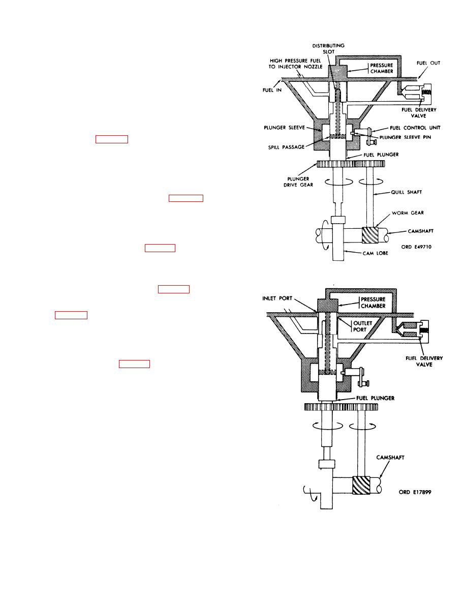
Figure 1-24. Fuel intake flow diagram. |
|
||
| ||||||||||
|
|
 TM 9-2910-226-34
1-22. Fuel Flow. Fuel flows from the vehicle fuel tank
to the fuel supply pump inlet. The fuel supply pump
delivers fuel through the fuel filters to a tee installed
in the fuel density compensator inlet port. From the
tee, fuel flows to the density compensator and to the
inlet of the hydraulic head. Fuel flows through the
hydraulic head and the head outlets to the engine
cylinders. Excess fuel from the hydraulic head
passes through the overflow valve, which maintains
a constant fuel pressure in the hydraulic head. The
constant flow of fuel through the hydraulic head not
only supplies fuel for injection but also serves as a
coolant for the hydraulic head. A pressure regulator
valve (JJ, fig. 1-16) in the density compensator
maintains pressure at 20 to 21 psi. Excess fuel from
the density compensator and hydraulic head flows
back to the vehicle fuel tank.
1-23. Fuel Pumping and Distribution. a. The fuel
injection pump camshaft is driven at engine crank-
shaft speed. As the camshaft rotates, the tappet
moves the fuel plunger (U, fig. 1-16) up and
down. The quill shaft, driven off the camshaft,
drives the plunger drive gear which rotates the fuel
plunger. When the camshaft has rotated twice, the
fuel plunger has rotated 360 and completed six fuel
injection strokes.
is on the base circle of the camshaft, the fuel plunger
is down, and fuel enters and fills the pressure
chamber. As the camshaft rotates, the fuel plunger
Figure 1-24. Fuel intake flow diagram.
closes off the inlet and outlet ports and is at the
beginning of delivery phase (fig. 1-25). The fuel in
the pressure chamber is pressurized and starts to
open the fuel delivery valve. At the delivery phase
fully open the fuel delivery valve. This highly
pressurized fuel then flows around the fuel plunger
annulus, through the distributing slot, which is now
alined with one of the six outlet passages, and out
the outlet passage to the injector nozzle. At the end
of delivery phase (fig. 1-27), after sufficient upward
movement of the fuel plunger, the spill passages
passes over the edge of the plunger sleeve. The fuel
pressure then escapes down the plunger vertical fuel
passage into the fuel sump which is at supply
pressure. The reduction of pressure causes the fuel
delivery valve to close.
Figure 1-25. Beginning of fuel delivery flow diagram.
1-27
|
|
Privacy Statement - Press Release - Copyright Information. - Contact Us |
