 |
|||
|
|
|||
|
Page Title:
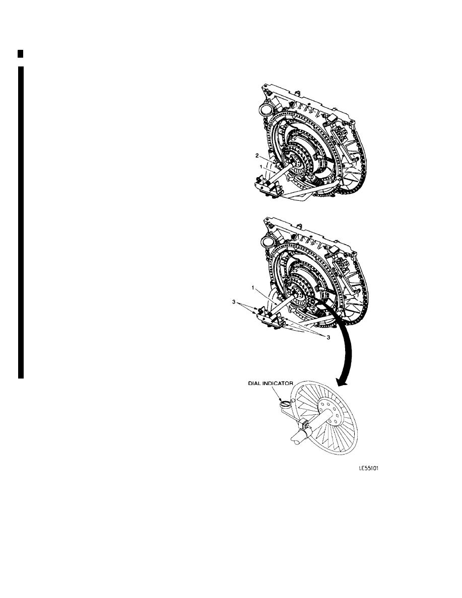
CHECK HORIZONTAL RUNOUT OF POWER TURBINE SHAFT |
|
||
| ||||||||||
|
|
 TM 9-2835-255-34
LOW PRESSURE TURBINE NOZZLE REPLACEMENT (Sheet 7 of 11)
7. CHECK HORIZONTAL RUNOUT OF POWER
TURBINE SHAFT (1).
a.
Move dial indicator assembly (2) to 9 o'clock
position and reset indicator gauge pointer to
zero.
b.
Rotate power turbine shaft (1) 180 degrees to
3 o'clock position and note direction of indica-
tor gauge pointer travel as shaft is rotated. Re-
cord dial reading.
c.
Rotate power turbine shaft (1) in reverse direc-
tion back to 9 o'clock position.
d.
Adjust runout fixture left and right side swivel
head screws (3) to obtain a dial reading equal
to one half the dial reading recorded in step b.
NOTE
Dial indicator gauge pointer must travel in
same direction as noted in step b. when
adjusting centering screws.
e.
Reset indicator gauge pointer to zero at 9
o'clock position, then rotate power turbine
shaft (1) 180 degrees to 3 o'clock position and
note dial reading.
f.
If zero reading is obtained at 3 o'clock posi-
tion, go to step 8.
g.
If zero reading is not obtained at 3 o'clock
position, repeat steps c., d., and e.
Go on to Sheet 8
6-98
Change 6
|
|
Privacy Statement - Press Release - Copyright Information. - Contact Us |