 |
|||
|
|
|||
|
Page Title:
INLET GUIDE VANES (IGVs) DO NOT MOVE WHEN IGV BELLCRANK IS TURNED BY HAND-continued |
|
||
| ||||||||||
|
|
 TM 9-2835-255-34
3-2. TROUBLESHOOTING - CONTINUED
g. INLET GUIDE VANE (IGV)
(1) ES-25. INLET GUIDE VANES (IGVs)
S Y S T E M - CONTINUED
DO NOT MOVE WHEN IGV BELLCRANK
I S TURNED BY HAND. - CONTINUED
CONTINUED FROM STEP 2
A.
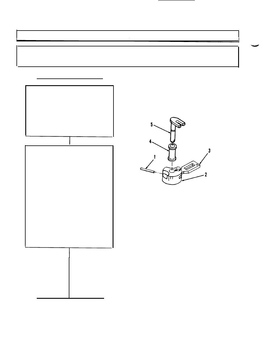
Remove spring pin (1).
If more than 1/4-inch is
exposed, use diagonal
pllers. If less than
1/4-inch, use 3/32-inch
punch.
B. Remove bellcrank (2)
with link (3) attached,
and bushing (4) from
inlet guide control (5).
A.
Place bellcrank (2),
with link (3) attached,
on flat surface. Start
new spring pin (1) into
bellcrank (2).
B. Put bushing 14) on new
inlet guide control (5),
and place inlet guide
control (5) into
bellcrank (2).
NOTE
When seated, spring pin (1)
should extend about 1/4-
inch out of bellcrank (2).
C.
Use 3\32-inch punch to
install spring pin (1)
in bellcrank (2) and
inlet guide control (5)
until seated.
CONTINUED ON NEXT PAGE
3-206
Change 5
|
|
Privacy Statement - Press Release - Copyright Information. - Contact Us |